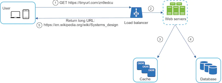
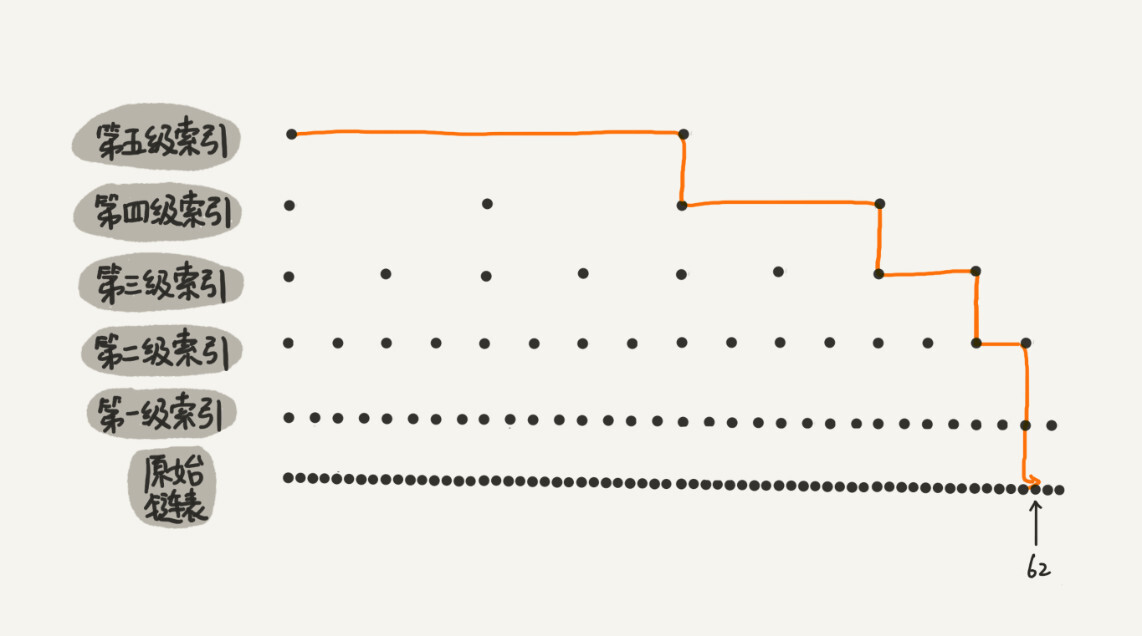
We are delighted that you have decided to join us in learning the system design interviews. System design interview questions are the most difficult to tackle among all the technical interviews. The questions require the interviewees to design an architecture for a software system, which could be a news feed, Google search, chat system, etc. These questions are intimidating, and there is no certain pattern to follow. The questions are usually very big scoped and vague. The processes are open-ended and unclear without a standard or correct answer.
Companies widely adopt system design interviews because the communication and problem-solving skills tested in these interviews are similar to those required by a software engineer's daily work. An interviewee is evaluated based on how she analyzes a vague problem and how she solves the problem step by step. The abilities tested also involve how she explains the idea, discusses with others, and evaluates and optimizes the system. In English, using "she" flows better than "he or she" or jumping between the two. To make reading easier, we use the feminine pronoun throughout this course. No disrespect is intended for male engineers.
The system design questions are open-ended. Just like in the real world, there are many differences and variations in the system. The desired outcome is to come up with an architecture to achieve system design goals. The discussions could go in different ways depending on the interviewer. Some interviewers may choose high-level architecture to cover all aspects; whereas some might choose one or more areas to focus on. Typically, system requirements, constraints and bottlenecks should be well understood to shape the direction of both the interviewer and interviewee.
The objective of this course is to provide a reliable strategy to approach the system design questions. The right strategy and knowledge are vital to the success of an interview.
This course provides solid knowledge in building a scalable system. The more knowledge gained from reading this course, the better you are equipped in solving the system design questions.
This course also provides a step by step framework on how to tackle a system design question. It provides many examples to illustrate the systematic approach with detailed steps that you can follow. With constant practice, you will be well-equipped to tackle system design interview questions.
CHAPTER 02
Join the Community
01
We created a members-only Discord group. It is designed for community discussions on the following topics:
System design fundamentals.
Showcasing design diagrams and getting feedback.
Finding mock interview buddies.
General chat with community members.
Come join us and introduce yourself to the community, today! Use the link below.
In this chapter, we focus on web crawler design: an interesting and classic system design interview question.
A web crawler is known as a robot or spider. It is widely used by search engines to discover new or updated content on the web. Content can be a web page, an image, a video, a PDF file, etc. A web crawler starts by collecting a few web pages and then follows links on those pages to collect new content. Figure 1 shows a visual example of the crawl process.
Figure 1
A crawler is used for many purposes:
Search engine indexing: This is the most common use case. A crawler collects web pages to create a local index for search engines. For example, Googlebot is the web crawler behind the Google search engine.
Web archiving: This is the process of collecting information from the web to preserve data for future uses. For instance, many national libraries run crawlers to archive web sites. Notable examples are the US Library of Congress [1] and the EU web archive [2].
Web mining: The explosive growth of the web presents an unprecedented opportunity for data mining. Web mining helps to discover useful knowledge from the internet. For example, top financial firms use crawlers to download shareholder meetings and annual reports to learn key company initiatives.
Web monitoring. The crawlers help to monitor copyright and trademark infringements over the Internet. For example, Digimarc [3] utilizes crawlers to discover pirated works and reports.
The complexity of developing a web crawler depends on the scale we intend to support. It could be either a small school project, which takes only a few hours to complete or a gigantic project that requires continuous improvement from a dedicated engineering team. Thus, we will explore the scale and features to support below.
Step 1 - Understand the problem and establish design scope
The basic algorithm of a web crawler is simple:
1. Given a set of URLs, download all the web pages addressed by the URLs.
2. Extract URLs from these web pages
3. Add new URLs to the list of URLs to be downloaded. Repeat these 3 steps.
Does a web crawler work truly as simple as this basic algorithm? Not exactly. Designing a vastly scalable web crawler is an extremely complex task. It is unlikely for anyone to design a massive web crawler within the interview duration. Before jumping into the design, we must ask questions to understand the requirements and establish design scope:
Candidate: What is the main purpose of the crawler? Is it used for search engine indexing, data mining, or something else? Interviewer: Search engine indexing.
Candidate: How many web pages does the web crawler collect per month? Interviewer: 1 billion pages.
Candidate: What content types are included? HTML only or other content types such as PDFs and images as well? Interviewer: HTML only.
Candidate: Shall we consider newly added or edited web pages? Interviewer: Yes, we should consider the newly added or edited web pages.
Candidate: Do we need to store HTML pages crawled from the web? Interviewer: Yes, up to 5 years
Candidate: How do we handle web pages with duplicate content? Interviewer: Pages with duplicate content should be ignored.
Above are some of the sample questions that you can ask your interviewer. It is important to understand the requirements and clarify ambiguities. Even if you are asked to design a straightforward product like a web crawler, you and your interviewer might not have the same assumptions.
Beside functionalities to clarify with your interviewer, it is also important to note down the following characteristics of a good web crawler:
Scalability: The web is very large. There are billions of web pages out there. Web crawling should be extremely efficient using parallelization.
Robustness: The web is full of traps. Bad HTML, unresponsive servers, crashes, malicious links, etc. are all common. The crawler must handle all those edge cases.
Politeness: The crawler should not make too many requests to a website within a short time interval.
Extensibility: The system is flexible so that minimal changes are needed to support new content types. For example, if we want to crawl image files in the future, we should not need to redesign the entire system.
Back of the envelope estimation
The following estimations are based on many assumptions, and it is important to communicate with the interviewer to be on the same page.
Assume 1 billion web pages are downloaded every month.
QPS: 1,000,000,000 / 30 days / 24 hours / 3600 seconds = ~400 pages per second.
Peak QPS = 2 * QPS = 800
Assume the average web page size is 500k.
1-billion-page x 500k = 500 TB storage per month. If you are unclear about digital storage units, go through “Power of 2” section in the "Back-of-the-envelope Estimation" chapter again.
Assuming data are stored for five years, 500 TB * 12 months * 5 years = 30 PB. A 30 PB storage is needed to store five-year content.
Step 2 - Propose high-level design and get buy-in
Once the requirements are clear, we move on to the high-level design. Inspired by previous studies on web crawling [4] [5], we propose a high-level design as shown in Figure 2.
Figure 2
First, we explore each design component to understand their functionalities. Then, we examine the crawler workflow step-by-step.
Seed URLs
A web crawler uses seed URLs as a starting point for the crawl process. For example, to crawl all web pages from a university’s website, an intuitive way to select seed URLs is to use the university’s domain name.
To crawl the entire web, we need to be creative in selecting seed URLs. A good seed URL serves as a good starting point that a crawler can utilize to traverse as many links as possible. The general strategy is to divide the entire URL space into smaller ones. The first proposed approach is based on locality as different countries may have different popular websites. Another way is to choose seed URLs based on topics; for example, we can divide URL space into shopping, sports, healthcare, etc. Seed URL selection is an open-ended question. You are not expected to give the perfect answer. Just think out loud.
URL Frontier
Most modern web crawlers split the crawl state into two: to be downloaded and already downloaded. The component that stores URLs to be downloaded is called the URL Frontier. You can refer to this as a First-in-First-out (FIFO) queue. For detailed information about the URL Frontier, refer to the deep dive.
HTML Downloader
The HTML downloader downloads web pages from the internet. Those URLs are provided by the URL Frontier.
DNS Resolver
To download a web page, a URL must be translated into an IP address. The HTML Downloader calls the DNS Resolver to get the corresponding IP address for the URL. For instance, URL www.wikipedia.org is converted to IP address 198.35.26.96 as of 3/5/2019.
Content Parser
After a web page is downloaded, it must be parsed and validated because malformed web pages could provoke problems and waste storage space. Implementing a content parser in a crawl server will slow down the crawling process. Thus, the content parser is a separate component.
Content Seen?
Online research [6] reveals that 29% of the web pages are duplicated contents, which may cause the same content to be stored multiple times. We introduce the “Content Seen?” data structure to eliminate data redundancy and shorten processing time. It helps to detect new content previously stored in the system. To compare two HTML documents, we can compare them character by character. However, this method is slow and time-consuming, especially when billions of web pages are involved. An efficient way to accomplish this task is to compare the hash values of the two web pages [7].
Content Storage
It is a storage system for storing HTML content. The choice of storage system depends on factors such as data type, data size, access frequency, life span, etc. Both disk and memory are used.
Most of the content is stored on disk because the data set is too big to fit in memory.
Popular content is kept in memory to reduce latency.
URL Extractor
URL Extractor parses and extracts links from HTML pages. Figure 3 shows an example of a link extraction process. Relative paths are converted to absolute URLs by adding the “https://en.wikipedia.org” prefix.
Figure 3
URL Filter
The URL filter excludes certain content types, file extensions, error links and URLs in “blacklisted” sites.
URL Seen?
“URL Seen?” is a data structure that keeps track of URLs that are visited before or already in the Frontier. “URL Seen?” helps to avoid adding the same URL multiple times as this can increase server load and cause potential infinite loops.
Bloom filter and hash table are common techniques to implement the “URL Seen?” component. We will not cover the detailed implementation of the bloom filter and hash table here. For more information, refer to the reference materials [4] [8].
URL Storage
URL Storage stores already visited URLs.
So far, we have discussed every system component. Next, we put them together to explain the workflow.
Web crawler workflow
To better explain the workflow step-by-step, sequence numbers are added in the design diagram as shown in Figure 4.
Figure 4
Step 1: Add seed URLs to the URL Frontier
Step 2: HTML Downloader fetches a list of URLs from URL Frontier.
Step 3: HTML Downloader gets IP addresses of URLs from DNS resolver and starts downloading.
Step 4: Content Parser parses HTML pages and checks if pages are malformed.
Step 5: After content is parsed and validated, it is passed to the “Content Seen?” component.
Step 6: “Content Seen” component checks if a HTML page is already in the storage.
If it is in the storage, this means the same content in a different URL has already been processed. In this case, the HTML page is discarded.
If it is not in the storage, the system has not processed the same content before. The content is passed to Link Extractor.
Step 7: Link extractor extracts links from HTML pages.
Step 8: Extracted links are passed to the URL filter.
Step 9: After links are filtered, they are passed to the “URL Seen?” component.
Step 10: “URL Seen” component checks if a URL is already in the storage, if yes, it is processed before, and nothing needs to be done.
Step 11: If a URL has not been processed before, it is added to the URL Frontier.
Step 3 - Design deep dive
Up until now, we have discussed the high-level design. Next, we will discuss the most important building components and techniques in depth:
Depth-first search (DFS) vs Breadth-first search (BFS)
URL frontier
HTML Downloader
Robustness
Extensibility
Detect and avoid problematic content
DFS vs BFS
You can think of the web as a directed graph where web pages serve as nodes and hyperlinks (URLs) as edges. The crawl process can be seen as traversing a directed graph from one web page to others. Two common graph traversal algorithms are DFS and BFS. However, DFS is usually not a good choice because the depth of DFS can be very deep.
BFS is commonly used by web crawlers and is implemented by a first-in-first-out (FIFO) queue. In a FIFO queue, URLs are dequeued in the order they are enqueued. However, this implementation has two problems:
Most links from the same web page are linked back to the same host. In Figure 5, all the links in wikipedia.com are internal links, making the crawler busy processing URLs from the same host (wikipedia.com). When the crawler tries to download web pages in parallel, Wikipedia servers will be flooded with requests. This is considered as “impolite”.
Figure 5
Standard BFS does not take the priority of a URL into consideration. The web is large and not every page has the same level of quality and importance. Therefore, we may want to prioritize URLs according to their page ranks, web traffic, update frequency, etc.
URL frontier
URL frontier helps to address these problems. A URL frontier is a data structure that stores URLs to be downloaded. The URL frontier is an important component to ensure politeness, URL prioritization, and freshness. A few noteworthy papers on URL frontier are mentioned in the reference materials [5] [9]. The findings from these papers are as follows:
Politeness
Generally, a web crawler should avoid sending too many requests to the same hosting server within a short period. Sending too many requests is considered as “impolite” or even treated as denial-of-service (DOS) attack. For example, without any constraint, the crawler can send thousands of requests every second to the same website. This can overwhelm the web servers.
The general idea of enforcing politeness is to download one page at a time from the same host. A delay can be added between two download tasks. The politeness constraint is implemented by maintain a mapping from website hostnames to download (worker) threads. Each downloader thread has a separate FIFO queue and only downloads URLs obtained from that queue. Figure 6 shows the design that manages politeness.
Figure 6
Queue router: It ensures that each queue (b1, b2, … bn) only contains URLs from the same host.
Mapping table: It maps each host to a queue.
Host
Queue
wikipedia.com
b1
apple.com
b2
...
...
nike.com
bn
Table 1
FIFO queues b1, b2 to bn: Each queue contains URLs from the same host.
Queue selector: Each worker thread is mapped to a FIFO queue, and it only downloads URLs from that queue. The queue selection logic is done by the Queue selector.
Worker thread 1 to N. A worker thread downloads web pages one by one from the same host. A delay can be added between two download tasks.
Priority
A random post from a discussion forum about Apple products carries very different weight than posts on the Apple home page. Even though they both have the “Apple” keyword, it is sensible for a crawler to crawl the Apple home page first.
We prioritize URLs based on usefulness, which can be measured by PageRank [10], website traffic, update frequency, etc. “Prioritizer” is the component that handles URL prioritization. Refer to the reference materials [5] [10] for in-depth information about this concept.
Figure 7 shows the design that manages URL priority.
Figure 7
Prioritizer: It takes URLs as input and computes the priorities.
Queue f1 to fn: Each queue has an assigned priority. Queues with high priority are selected with higher probability.
Queue selector: Randomly choose a queue with a bias towards queues with higher priority.
Figure 8 presents the URL frontier design, and it contains two modules:
Front queues: manage prioritization
Back queues: manage politeness
Figure 8
Freshness
Web pages are constantly being added, deleted, and edited. A web crawler must periodically recrawl downloaded pages to keep our data set fresh. Recrawl all the URLs is time-consuming and resource intensive. Few strategies to optimize freshness are listed as follows:
Recrawl based on web pages’ update history.
Prioritize URLs and recrawl important pages first and more frequently.
Storage for URL Frontier
In real-world crawl for search engines, the number of URLs in the frontier could be hundreds of millions [4]. Putting everything in memory is neither durable nor scalable. Keeping everything in the disk is undesirable neither because the disk is slow; and it can easily become a bottleneck for the crawl.
We adopted a hybrid approach. The majority of URLs are stored on disk, so the storage space is not a problem. To reduce the cost of reading from the disk and writing to the disk, we maintain buffers in memory for enqueue/dequeue operations. Data in the buffer is periodically written to the disk.
HTML Downloader
The HTML Downloader downloads web pages from the internet using the HTTP protocol. Before discussing the HTML Downloader, we look at Robots Exclusion Protocol first.
Robots.txt
Robots.txt, called Robots Exclusion Protocol, is a standard used by websites to communicate with crawlers. It specifies what pages crawlers are allowed to download. Before attempting to crawl a web site, a crawler should check its corresponding robots.txt first and follow its rules.
To avoid repeat downloads of robots.txt file, we cache the results of the file. The file is downloaded and saved to cache periodically. Here is a piece of robots.txt file taken from https://www.amazon.com/robots.txt. Some of the directories like creatorhub are disallowed for Google bot.
Besides robots.txt, performance optimization is another important concept we will cover for the HTML downloader.
Performance optimization
Below is a list of performance optimizations for HTML downloader.
1. Distributed crawl
To achieve high performance, crawl jobs are distributed into multiple servers, and each server runs multiple threads. The URL space is partitioned into smaller pieces; so, each downloader is responsible for a subset of the URLs. Figure 9 shows an example of a distributed crawl.
Figure 9
2. Cache DNS Resolver
DNS Resolver is a bottleneck for crawlers because DNS requests might take time due to the synchronous nature of many DNS interfaces. DNS response time ranges from 10ms to 200ms. Once a request to DNS is carried out by a crawler thread, other threads are blocked until the first request is completed. Maintaining our DNS cache to avoid calling DNS frequently is an effective technique for speed optimization. Our DNS cache keeps the domain name to IP address mapping and is updated periodically by cron jobs.
3. Locality
Distribute crawl servers geographically. When crawl servers are closer to website hosts, crawlers experience faster download time. Design locality applies to most of the system components: crawl servers, cache, queue, storage, etc.
4. Short timeout
Some web servers respond slowly or may not respond at all. To avoid long wait time, a maximal wait time is specified. If a host does not respond within a predefined time, the crawler will stop the job and crawl some other pages.
Robustness
Besides performance optimization, robustness is also an important consideration. We present a few approaches to improve the system robustness:
Consistent hashing: This helps to distribute loads among downloaders. A new downloader server can be added or removed using consistent hashing. Refer to the "Design consistent hashing" chapter for more details.
Save crawl states and data: To guard against failures, crawl states and data are written to a storage system. A disrupted crawl can be restarted easily by loading saved states and data.
Exception handling: Errors are inevitable and common in a large-scale system. The crawler must handle exceptions gracefully without crashing the system.
Data validation: This is an important measure to prevent system errors.
Extensibility
As almost every system evolves, one of the design goals is to make the system flexible enough to support new content types. The crawler can be extended by plugging in new modules. Figure 10 shows how to add new modules.
Figure 10
PNG Downloader module is plugged-in to download PNG files.
Web Monitor module is added to monitor the web and prevent copyright and trademark infringements.
Detect and avoid problematic content
This section discusses the detection and prevention of redundant, meaningless, or harmful content.
1. Redundant content
As discussed previously, nearly 30% of the web pages are duplicates. Hashes or checksums help to detect duplication [11].
2. Spider traps
A spider trap is a web page that causes a crawler in an infinite loop. For instance, an infinite deep directory structure is listed as follows: http://www.spidertrapexample.com/foo/bar/foo/bar/foo/bar/...
Such spider traps can be avoided by setting a maximal length for URLs. However, no one-size-fits-all solution exists to detect spider traps. Websites containing spider traps are easy to identify due to an unusually large number of web pages discovered on such websites. It is hard to develop automatic algorithms to avoid spider traps; however, a user can manually verify and identify a spider trap, and either exclude those websites from the crawler or apply some customized URL filters.
3. Data noise
Some of the contents have little or no value, such as advertisements, code snippets, spam URLs, etc. Those contents are not useful for crawlers and should be excluded if possible.
Step 4 - Wrap up
In this chapter, we first discussed the characteristics of a good crawler: scalability, politeness, extensibility, and robustness. Then, we proposed a design and discussed key components. Building a scalable web crawler is not a trivial task because the web is enormously large and full of traps. Even though we have covered many topics, we still miss many relevant talking points:
Server-side rendering: Numerous websites use scripts like JavaScript, AJAX, etc to generate links on the fly. If we download and parse web pages directly, we will not be able to retrieve dynamically generated links. To solve this problem, we perform server-side rendering (also called dynamic rendering) first before parsing a page [12].
Filter out unwanted pages: With finite storage capacity and crawl resources, an anti-spam component is beneficial in filtering out low quality and spam pages [13] [14].
Database replication and sharding: Techniques like replication and sharding are used to improve the data layer availability, scalability, and reliability.
Horizontal scaling: For large scale crawl, hundreds or even thousands of servers are needed to perform download tasks. The key is to keep servers stateless.
Availability, consistency, and reliability: These concepts are at the core of any large system’s success.
Analytics: Collecting and analyzing data are important parts of any system because data is key ingredient for fine-tuning.
Congratulations on getting this far! Now give yourself a pat on the back. Good job!
[10] L. Page, S. Brin, R. Motwani, and T. Winograd, “The PageRank citation ranking: Bringing order to the web,” Technical Report, Stanford University, 1998.
[11] Burton Bloom. Space/time trade-offs in hash coding with allowable errors. Communications of the ACM, 13(7), pages 422--426, July 1970.
[13] T. Urvoy, T. Lavergne, and P. Filoche, “Tracking web spam with hidden style similarity,” in Proceedings of the 2nd International Workshop on Adversarial Information Retrieval on the Web, 2006.
[14] H.-T. Lee, D. Leonard, X. Wang, and D. Loguinov, “IRLbot: Scaling to 6 billion pages and beyond,” in Proceedings of the 17th International World Wide Web Conference, 2008.
CHAPTER 04
Design A Notification System
11
A notification system has already become a very popular feature for many applications in recent years. A notification alerts a user with important information like breaking news, product updates, events, offerings, etc. It has become an indispensable part of our daily life. In this chapter, you are asked to design a notification system.
A notification is more than just mobile push notification. Three types of notification formats are: mobile push notification, SMS message, and Email. Figure 1 shows an example of each of these notifications.
Figure 1
Step 1 - Understand the problem and establish design scope
Building a scalable system that sends out millions of notifications a day is not an easy task. It requires a deep understanding of the notification ecosystem. The interview question is purposely designed to be open-ended and ambiguous, and it is your responsibility to ask questions to clarify the requirements.
Candidate: What types of notifications does the system support? Interviewer: Push notification, SMS message, and email.
Candidate: Is it a real-time system? Interviewer: Let us say it is a soft real-time system. We want a user to receive notifications as soon as possible. However, if the system is under a high workload, a slight delay is acceptable.
Candidate: What are the supported devices? Interviewer: iOS devices, android devices, and laptop/desktop.
Candidate: What triggers notifications? Interviewer: Notifications can be triggered by client applications. They can also be scheduled on the server-side.
Candidate: Will users be able to opt-out? Interviewer: Yes, users who choose to opt-out will no longer receive notifications.
Candidate: How many notifications are sent out each day? Interviewer: 10 million mobile push notifications, 1 million SMS messages, and 5 million emails.
Step 2 - Propose high-level design and get buy-in
This section shows the high-level design that supports various notification types: iOS push notification, Android push notification, SMS message, and Email. It is structured as follows:
Different types of notifications
Contact info gathering flow
Notification sending/receiving flow
Different types of notifications
We start by looking at how each notification type works at a high level.
iOS push notification
Figure 2
We primary need three components to send an iOS push notification:
Provider. A provider builds and sends notification requests to Apple Push Notification Service (APNS). To construct a push notification, the provider provides the following data:
Device token: This is a unique identifier used for sending push notifications.
Payload: This is a JSON dictionary that contains a notification’s payload. Here is an example:
Code
{
   "aps":{
      "alert":{
         "title":"Game Request",
         "body":"Bob wants to play chess",
         "action-loc-key":"PLAY"
      },
      "badge":5
   }
}
APNS: This is a remote service provided by Apple to propagate push notifications to iOS devices.
iOS Device: It is the end client, which receives push notifications.
Android push notification
Android adopts a similar notification flow. Instead of using APNs, Firebase Cloud Messaging (FCM) is commonly used to send push notifications to android devices.
Figure 3
SMS message
For SMS messages, third party SMS services like Twilio [1], Nexmo [2], and many others are commonly used. Most of them are commercial services.
Figure 4
Email
Although companies can set up their own email servers, many of them opt for commercial email services. Sendgrid [3] and Mailchimp [4] are among the most popular email services, which offer a better delivery rate and data analytics.
Figure 5
Figure 6 shows the design after including all the third-party services.
Figure 6
Contact info gathering flow
To send notifications, we need to gather mobile device tokens, phone numbers, or email addresses. As shown in Figure 7, when a user installs our app or signs up for the first time, API servers collect user contact info and store it in the database.
Figure 7
Figure 8 shows simplified database tables to store contact info. Email addresses and phone numbers are stored in the user table, whereas device tokens are stored in the device table. A user can have multiple devices, indicating that a push notification can be sent to all the user devices.
Figure 8
Notification sending/receiving flow
We will first present the initial design; then, propose some optimizations.
High-level design
Figure 9 shows the design, and each system component is explained below.
Figure 9
Service 1 to N: A service can be a micro-service, a cron job, or a distributed system that triggers notification sending events. For example, a billing service sends emails to remind customers of their due payment or a shopping website tells customers that their packages will be delivered tomorrow via SMS messages.
Notification system: The notification system is the centerpiece of sending/receiving notifications. Starting with something simple, only one notification server is used. It provides APIs for services 1 to N, and builds notification payloads for third party services.
Third-party services: Third party services are responsible for delivering notifications to users. While integrating with third-party services, we need to pay extra attention to extensibility. Good extensibility means a flexible system that can easily plugging or unplugging of a third-party service. Another important consideration is that a third-party service might be unavailable in new markets or in the future. For instance, FCM is unavailable in China. Thus, alternative third-party services such as Jpush, PushY, etc are used there.
iOS, Android, SMS, Email: Users receive notifications on their devices.
Three problems are identified in this design:
Single point of failure (SPOF): A single notification server means SPOF.
Hard to scale: The notification system handles everything related to push notifications in one server. It is challenging to scale databases, caches, and different notification processing components independently.
Performance bottleneck: Processing and sending notifications can be resource intensive. For example, constructing HTML pages and waiting for responses from third party services could take time. Handling everything in one system can result in the system overload, especially during peak hours.
High-level design (improved)
After enumerating challenges in the initial design, we improve the design as listed below:
Move the database and cache out of the notification server.
Add more notification servers and set up automatic horizontal scaling.
Introduce message queues to decouple the system components.
Figure 10 shows the improved high-level design.
Figure 10
The best way to go through the above diagram is from left to right:
Service 1 to N: They represent different services that send notifications via APIs provided by notification servers.
Notification servers: They provide the following functionalities:
Provide APIs for services to send notifications. Those APIs are only accessible internally or by verified clients to prevent spams.
Carry out basic validations to verify emails, phone numbers, etc.
Query the database or cache to fetch data needed to render a notification.
Put notification data to message queues for parallel processing.
Cache: User info, device info, notification templates are cached.
DB: It stores data about user, notification, settings, etc.
Message queues: They remove dependencies between components. Message queues serve as buffers when high volumes of notifications are to be sent out. Each notification type is assigned with a distinct message queue so an outage in one third-party service will not affect other notification types.
Workers: Workers are a list of servers that pull notification events from message queues and send them to the corresponding third-party services.
Third-party services: Already explained in the initial design.
iOS, Android, SMS, Email: Already explained in the initial design.
Next, let us examine how every component works together to send a notification:
1. A service calls APIs provided by notification servers to send notifications.
2. Notification servers fetch metadata such as user info, device token, and notification setting from the cache or database.
3. A notification event is sent to the corresponding queue for processing. For instance, an iOS push notification event is sent to the iOS PN queue.
4. Workers pull notification events from message queues.
5. Workers send notifications to third party services.
6. Third-party services send notifications to user devices.
Step 3 - Design deep dive
In the high-level design, we discussed different types of notifications, contact info gathering flow, and notification sending/receiving flow. We will explore the following in deep dive:
Reliability.
Additional component and considerations: notification template, notification settings, rate limiting, retry mechanism, security in push notifications, monitor queued notifications and event tracking.
Updated design.
Reliability
We must answer a few important reliability questions when designing a notification system in distributed environments.
How to prevent data loss?
One of the most important requirements in a notification system is that it cannot lose data. Notifications can usually be delayed or re-ordered, but never lost. To satisfy this requirement, the notification system persists notification data in a database and implements a retry mechanism. The notification log database is included for data persistence, as shown in Figure 11.
Figure 11
Will recipients receive a notification exactly once?
The short answer is no. Although notification is delivered exactly once most of the time, the distributed nature could result in duplicate notifications. To reduce the duplication occurrence, we introduce a dedupe mechanism and handle each failure case carefully. Here is a simple dedupe logic:
When a notification event first arrives, we check if it is seen before by checking the event ID. If it is seen before, it is discarded. Otherwise, we will send out the notification. For interested readers to explore why we cannot have exactly once delivery, refer to the reference material [5].
Additional components and considerations
We have discussed how to collect user contact info, send, and receive a notification. A notification system is a lot more than that. Here we discuss additional components including template reusing, notification settings, event tracking, system monitoring, rate limiting, etc.
Notification template
A large notification system sends out millions of notifications per day, and many of these notifications follow a similar format. Notification templates are introduced to avoid building every notification from scratch. A notification template is a preformatted notification to create your unique notification by customizing parameters, styling, tracking links, etc. Here is an example template of push notifications.
Code
BODY:
You dreamed of it. We dared it. [ITEM NAME] is back — only until [DATE].

CTA:
Order Now. Or, Save My [ITEM NAME]
The benefits of using notification templates include maintaining a consistent format, reducing the margin error, and saving time.
Notification setting
Users generally receive way too many notifications daily and they can easily feel overwhelmed. Thus, many websites and apps give users fine-grained control over notification settings. This information is stored in the notification setting table, with the following fields:
user_id bigInt
channel varchar # push notification, email or SMS
opt_in boolean # opt-in to receive notification
Before any notification is sent to a user, we first check if a user is opted-in to receive this type of notification.
Rate limiting
To avoid overwhelming users with too many notifications, we can limit the number of notifications a user can receive. This is important because receivers could turn off notifications completely if we send too often.
Retry mechanism
When a third-party service fails to send a notification, the notification will be added to the message queue for retrying. If the problem persists, an alert will be sent out to developers.
Security in push notifications
For iOS or Android apps, appKey and appSecret are used to secure push notification APIs [6]. Only authenticated or verified clients are allowed to send push notifications using our APIs. Interested users should refer to the reference material [6].
Monitor queued notifications
A key metric to monitor is the total number of queued notifications. If the number is large, the notification events are not processed fast enough by workers. To avoid delay in the notification delivery, more workers are needed. Figure 12 (credit to [7]) shows an example of queued messages to be processed.
Figure 12
Events tracking
Notification metrics, such as open rate, click rate, and engagement are important in understanding customer behaviors. Analytics service implements events tracking. Integration between the notification system and the analytics service is usually required. Figure 13 shows an example of events that might be tracked for analytics purposes.
Figure 13
Updated design
Putting everything together, Figure 14 shows the updated notification system design.
Figure 14
In this design, many new components are added in comparison with the previous design.
The notification servers are equipped with two more critical features: authentication and rate-limiting.
We also add a retry mechanism to handle notification failures. If the system fails to send notifications, they are put back in the messaging queue and the workers will retry for a predefined number of times.
Furthermore, notification templates provide a consistent and efficient notification creation process.
Finally, monitoring and tracking systems are added for system health checks and future improvements.
Step 4 - Wrap up
Notifications are indispensable because they keep us posted with important information. It could be a push notification about your favorite movie on Netflix, an email about discounts on new products, or a message about your online shopping payment confirmation.
In this chapter, we described the design of a scalable notification system that supports multiple notification formats: push notification, SMS message, and email. We adopted message queues to decouple system components.
Besides the high-level design, we dug deep into more components and optimizations.
Reliability: We proposed a robust retry mechanism to minimize the failure rate.
Security: AppKey/appSecret pair is used to ensure only verified clients can send notifications.
Tracking and monitoring: These are implemented in any stage of a notification flow to capture important stats.
Respect user settings: Users may opt-out of receiving notifications. Our system checks user settings first before sending notifications.
Rate limiting: Users will appreciate a frequency capping on the number of notifications they receive.
Congratulations on getting this far! Now give yourself a pat on the back. Good job!
In this chapter, you are asked to design a news feed system. What is news feed? According to the Facebook help page, “News feed is the constantly updating list of stories in the middle of your home page. News Feed includes status updates, photos, videos, links, app activity, and likes from people, pages, and groups that you follow on Facebook” [1]. This is a popular interview question. Similar questions commonly asked are to: design Facebook news feed, Instagram feed, Twitter timeline, etc.
Figure 1
Step 1 - Understand the problem and establish design scope
The first set of clarification questions are to understand what the interviewer has in mind when she asks you to design a news feed system. At the very least, you should figure out what features to support. Here is an example of candidate-interviewer interaction:
Candidate: Is this a mobile app? Or a web app? Or both? Interviewer: Both
Candidate: What are the important features? Interview: A user can publish a post and see her friends’ posts on the news feed page.
Candidate: Is the news feed sorted by reverse chronological order or any particular order such as topic scores? For instance, posts from your close friends have higher scores. Interviewer: To keep things simple, let us assume the feed is sorted by reverse chronological order.
Candidate: How many friends can a user have? Interviewer: 5000
Candidate: What is the traffic volume? Interviewer: 10 million DAU
Candidate: Can feed contain images, videos, or just text? Interviewer: It can contain media files, including both images and videos.
Now you have gathered the requirements, we focus on designing the system.
Step 2 - Propose high-level design and get buy-in
The design is divided into two flows: feed publishing and news feed building.
Feed publishing: when a user publishes a post, corresponding data is written into cache and database. A post is populated to her friends’ news feed.
Newsfeed building: for simplicity, let us assume the news feed is built by aggregating friends’ posts in reverse chronological order.
Newsfeed APIs
The news feed APIs are the primary ways for clients to communicate with servers. Those APIs are HTTP based that allow clients to perform actions, which include posting a status, retrieving news feed, adding friends, etc. We discuss two most important APIs: feed publishing API and news feed retrieval API.
Feed publishing API
To publish a post, a HTTP POST request will be sent to the server. The API is shown below:
POST /v1/me/feed
Params:
content: content is the text of the post.
auth_token: it is used to authenticate API requests.
Newsfeed retrieval API
The API to retrieve news feed is shown below:
GET /v1/me/feed
Params:
auth_token: it is used to authenticate API requests.
Feed publishing
Figure 2 shows the high-level design of the feed publishing flow.
Figure 2
User: a user can view news feeds on a browser or mobile app. A user makes a post with content “Hello” through API:
/v1/me/feed?content=Hello&auth_token={auth_token}
Load balancer: distribute traffic to web servers.
Web servers: web servers redirect traffic to different internal services.
Post service: persist post in the database and cache.
Fanout service: push new content to friends’ news feed. Newsfeed data is stored in the cache for fast retrieval.
Notification service: inform friends that new content is available and send out push notifications.
Newsfeed building
In this section, we discuss how news feed is built behind the scenes. Figure 3 shows the high-level design:
Figure 3
User: a user sends a request to retrieve her news feed. The request looks like this: /v1/me/feed.
Load balancer: load balancer redirects traffic to web servers.
Web servers: web servers route requests to newsfeed service.
Newsfeed service: news feed service fetches news feed from the cache.
Newsfeed cache: store news feed IDs needed to render the news feed.
Step 3 - Design deep dive
The high-level design briefly covered two flows: feed publishing and news feed building. Here, we discuss those topics in more depth.
Feed publishing deep dive
Figure 4 outlines the detailed design for feed publishing. We have discussed most of components in high-level design, and we will focus on two components: web servers and fanout service.
Figure 4
Web servers
Besides communicating with clients, web servers enforce authentication and rate-limiting. Only users signed in with valid auth_token are allowed to make posts. The system limits the number of posts a user can make within a certain period, vital to prevent spam and abusive content.
Fanout service
Fanout is the process of delivering a post to all friends. Two types of fanout models are: fanout on write (also called push model) and fanout on read (also called pull model). Both models have pros and cons. We explain their workflows and explore the best approach to support our system.
Fanout on write. With this approach, news feed is pre-computed during write time. A new post is delivered to friends’ cache immediately after it is published.
Pros:
The news feed is generated in real-time and can be pushed to friends immediately.
Fetching news feed is fast because the news feed is pre-computed during write time.
Cons:
If a user has many friends, fetching the friend list and generating news feeds for all of them are slow and time consuming. It is called hotkey problem.
For inactive users or those rarely log in, pre-computing news feeds waste computing resources.
Fanout on read. The news feed is generated during read time. This is an on-demand model. Recent posts are pulled when a user loads her home page.
Pros:
For inactive users or those who rarely log in, fanout on read works better because it will not waste computing resources on them.
Data is not pushed to friends so there is no hotkey problem.
Cons:
Fetching the news feed is slow as the news feed is not pre-computed.
We adopt a hybrid approach to get benefits of both approaches and avoid pitfalls in them. Since fetching the news feed fast is crucial, we use a push model for the majority of users. For celebrities or users who have many friends/followers, we let followers pull news content on-demand to avoid system overload. Consistent hashing is a useful technique to mitigate the hotkey problem as it helps to distribute requests/data more evenly.
Let us take a close look at the fanout service as shown in Figure 5.
Figure 5
The fanout service works as follows:
1. Fetch friend IDs from the graph database. Graph databases are suited for managing friend relationship and friend recommendations. Interested readers wishing to learn more about this concept should refer to the reference material [2].
2. Get friends info from the user cache. The system then filters out friends based on user settings. For example, if you mute someone, her posts will not show up on your news feed even though you are still friends. Another reason why posts may not show is that a user could selectively share information with specific friends or hide it from other people.
3. Send friends list and new post ID to the message queue.
4. Fanout workers fetch data from the message queue and store news feed data in the news feed cache. You can think of the news feed cache as a <post_id, user_id> mapping table. Whenever a new post is made, it will be appended to the news feed table as shown in Figure 6. The memory consumption can become very large if we store the entire user and post objects in the cache. Thus, only IDs are stored. To keep the memory size small, we set a configurable limit. The chance of a user scrolling through thousands of posts in news feed is slim. Most users are only interested in the latest content, so the cache miss rate is low.
5. Store <post_id, user_id > in news feed cache. Figure 6 shows an example of what the news feed looks like in cache.
post_id
user_id
post_id
user_id
post_id
user_id
post_id
user_id
post_id
user_id
post_id
user_id
post_id
user_id
post_id
user_id
Figure 6
Newsfeed retrieval deep dive
Figure 7 illustrates the detailed design for news feed retrieval.
Figure 7
As shown in Figure 7, media content (images, videos, etc.) are stored in CDN for fast retrieval. Let us look at how a client retrieves news feed.
1. A user sends a request to retrieve her news feed. The request looks like this: /v1/me/feed
2. The load balancer redistributes requests to web servers.
3. Web servers call the news feed service to fetch news feeds.
4. News feed service gets a list post IDs from the news feed cache.
5. A user’s news feed is more than just a list of feed IDs. It contains username, profile picture, post content, post image, etc. Thus, the news feed service fetches the complete user and post objects from caches (user cache and post cache) to construct the fully hydrated news feed.
6. The fully hydrated news feed is returned in JSON format back to the client for rendering.
Cache architecture
Cache is extremely important for a news feed system. We divide the cache tier into 5 layers as shown in Figure 8.
Figure 8
News Feed: It stores IDs of news feeds.
Content: It stores every post data. Popular content is stored in hot cache.
Social Graph: It stores user relationship data.
Action: It stores info about whether a user liked a post, replied a post, or took other actions on a post.
Counters: It stores counters for like, reply, follower, following, etc.
Step 4 - Wrap up
In this chapter, we designed a news feed system. Our design contains two flows: feed publishing and news feed retrieval.
Like any system design interview questions, there is no perfect way to design a system. Every company has its unique constraints, and you must design a system to fit those constraints. Understanding the tradeoffs of your design and technology choices are important. If there are a few minutes left, you can talk about scalability issues. To avoid duplicated discussion, only high-level talking points are listed below.
Scaling the database:
Vertical scaling vs Horizontal scaling
SQL vs NoSQL
Master-slave replication
Read replicas
Consistency models
Database sharding
Other talking points:
Keep web tier stateless
Cache data as much as you can
Support multiple data centers
Lose couple components with message queues
Monitor key metrics. For instance, QPS during peak hours and latency while users refreshing their news feed are interesting to monitor.
Congratulations on getting this far! Now give yourself a pat on the back. Good job!
In this chapter we explore the design of a chat system. Almost everyone uses a chat app. Figure 1 shows some of the most popular apps in the marketplace.
Figure 1
A chat app performs different functions for different people. It is extremely important to nail down the exact requirements. For example, you do not want to design a system that focuses on group chat when the interviewer has one-on-one chat in mind. It is important to explore the feature requirements.
Step 1 - Understand the problem and establish design scope
It is vital to agree on the type of chat app to design. In the marketplace, there are one-on-one chat apps like Facebook Messenger, WeChat, and WhatsApp, office chat apps that focus on group chat like Slack, or game chat apps, like Discord, that focus on large group interaction and low voice chat latency.
The first set of clarification questions should nail down what the interviewer has in mind exactly when she asks you to design a chat system. At the very least, figure out if you should focus on a one-on-one chat or group chat app. Some questions you might ask are as follows:
Candidate: What kind of chat app shall we design? 1 on 1 or group based? Interviewer: It should support both 1 on 1 and group chat.
Candidate: Is this a mobile app? Or a web app? Or both? Interviewer: Both.
Candidate: What is the scale of this app? A startup app or massive scale? Interviewer: It should support 50 million daily active users (DAU).
Candidate: For group chat, what is the group member limit? Interviewer: A maximum of 100 people
Candidate: What features are important for the chat app? Can it support attachment? Interviewer: 1 on 1 chat, group chat, online indicator. The system only supports text messages.
Candidate: Is there a message size limit? Interviewer: Yes, text length should be less than 100,000 characters long.
Candidate: Is end-to-end encryption required? Interviewer: Not required for now but we will discuss that if time allows.
Candidate: How long shall we store the chat history? Interviewer: Forever.
In the chapter, we focus on designing a chat app like Facebook messenger, with an emphasis on the following features:
A one-on-one chat with low delivery latency
Small group chat (max of 100 people)
Online presence
Multiple device support. The same account can be logged in to multiple accounts at the same time.
Push notifications
It is also important to agree on the design scale. We will design a system that supports 50 million DAU.
Step 2 - Propose high-level design and get buy-in
To develop a high-quality design, we should have a basic knowledge of how clients and servers communicate. In a chat system, clients can be either mobile applications or web applications. Clients do not communicate directly with each other. Instead, each client connects to a chat service, which supports all the features mentioned above. Let us focus on fundamental operations. The chat service must support the following functions:
Receive messages from other clients.
Find the right recipients for each message and relay the message to the recipients.
If a recipient is not online, hold the messages for that recipient on the server until she is online.
Figure 2 shows the relationships between clients (sender and receiver) and the chat service.
Figure 2
When a client intends to start a chat, it connects the chats service using one or more network protocols. For a chat service, the choice of network protocols is important. Let us discuss this with the interviewer.
Requests are initiated by the client for most client/server applications. This is also true for the sender side of a chat application. In Figure 2, when the sender sends a message to the receiver via the chat service, it uses the time-tested HTTP protocol, which is the most common web protocol. In this scenario, the client opens a HTTP connection with the chat service and sends the message, informing the service to send the message to the receiver. The keep-alive is efficient for this because the keep-alive header allows a client to maintain a persistent connection with the chat service. It also reduces the number of TCP handshakes. HTTP is a fine option on the sender side, and many popular chat applications such as Facebook [1] used HTTP initially to send messages.
However, the receiver side is a bit more complicated. Since HTTP is client-initiated, it is not trivial to send messages from the server. Over the years, many techniques are used to simulate a server-initiated connection: polling, long polling, and WebSocket. Those are important techniques widely used in system design interviews so let us examine each of them.
Polling
As shown in Figure 3, polling is a technique that the client periodically asks the server if there are messages available. Depending on polling frequency, polling could be costly. It could consume precious server resources to answer a question that offers no as an answer most of the time.
Figure 3
Long polling
Because polling could be inefficient, the next progression is long polling (Figure 4).
Figure 4
In long polling, a client holds the connection open until there are actually new messages available or a timeout threshold has been reached. Once the client receives new messages, it immediately sends another request to the server, restarting the process. Long polling has a few drawbacks:
Sender and receiver may not connect to the same chat server. HTTP based servers are usually stateless. If you use round robin for load balancing, the server that receives the message might not have a long-polling connection with the client who receives the message.
A server has no good way to tell if a client is disconnected.
It is inefficient. If a user does not chat much, long polling still makes periodic connections after timeouts.
WebSocket
WebSocket is the most common solution for sending asynchronous updates from server to client. Figure 5 shows how it works.
Figure 5
WebSocket connection is initiated by the client. It is bi-directional and persistent. It starts its life as a HTTP connection and could be “upgraded” via some well-defined handshake to a WebSocket connection. Through this persistent connection, a server could send updates to a client. WebSocket connections generally work even if a firewall is in place. This is because they use port 80 or 443 which are also used by HTTP/HTTPS connections.
Earlier we said that on the sender side HTTP is a fine protocol to use, but since WebSocket is bidirectional, there is no strong technical reason not to use it also for sending. Figure 6 shows how WebSockets (ws) is used for both sender and receiver sides.
Figure 6
By using WebSocket for both sending and receiving, it simplifies the design and makes implementation on both client and server more straightforward. Since WebSocket connections are persistent, efficient connection management is critical on the server-side.
High-level design
Just now we mentioned that WebSocket was chosen as the main communication protocol between the client and server for its bidirectional communication, it is important to note that everything else does not have to be WebSocket. In fact, most features (sign up, login, user profile, etc) of a chat application could use the traditional request/response method over HTTP. Let us drill in a bit and look at the high-level components of the system.
As shown in Figure 7, the chat system is broken down into three major categories: stateless services, stateful services, and third-party integration.
Figure 7
Stateless Services
Stateless services are traditional public-facing request/response services, used to manage the login, signup, user profile, etc. These are common features among many websites and apps.
Stateless services sit behind a load balancer whose job is to route requests to the correct services based on the request paths. These services can be monolithic or individual microservices. We do not need to build many of these stateless services by ourselves as there are services in the market that can be integrated easily. The one service that we will discuss more in deep dive is the service discovery. Its primary job is to give the client a list of DNS host names of chat servers that the client could connect to.
Stateful Service
The only stateful service is the chat service. The service is stateful because each client maintains a persistent network connection to a chat server. In this service, a client normally does not switch to another chat server as long as the server is still available. The service discovery coordinates closely with the chat service to avoid server overloading. We will go into detail in deep dive.
Third-party integration
For a chat app, push notification is the most important third-party integration. It is a way to inform users when new messages have arrived, even when the app is not running. Proper integration of push notification is crucial. Refer to "Design a notification system" chapter for more information.
Scalability
On a small scale, all services listed above could fit in one server. Even at the scale we design for, it is in theory possible to fit all user connections in one modern cloud server. The number of concurrent connections that a server can handle will most likely be the limiting factor. In our scenario, at 1M concurrent users, assuming each user connection needs 10K of memory on the server (this is a very rough figure and very dependent on the language choice), it only needs about 10GB of memory to hold all the connections on one box.
If we propose a design where everything fits in one server, this may raise a big red flag in the interviewer’s mind. No technologist would design such a scale in a single server. Single server design is a deal breaker due to many factors. The single point of failure is the biggest among them.
However, it is perfectly fine to start with a single server design. Just make sure the interviewer knows this is a starting point. Putting everything we mentioned together, Figure 8 shows the adjusted high-level design.
Figure 8
In Figure 8, the client maintains a persistent WebSocket connection to a chat server for real-time messaging.
API servers handle everything including user login, signup, change profile, etc.
Notification servers send push notifications.
Finally, the key-value store is used to store chat history. When an offline user comes online, she will see all her previous chat history.
Storage
At this point, we have servers ready, services up running and third-party integrations complete. Deep down the technical stack is the data layer. Data layer usually requires some effort to get it correct. An important decision we must make is to decide on the right type of database to use: relational databases or NoSQL databases? To make an informed decision, we will examine the data types and read/write patterns.
Two types of data exist in a typical chat system. The first is generic data, such as user profile, setting, user friends list. These data are stored in robust and reliable relational databases. Replication and sharding are common techniques to satisfy availability and scalability requirements.
The second is unique to chat systems: chat history data. It is important to understand the read/write pattern.
The amount of data is enormous for chat systems. A previous study [2] reveals that Facebook messenger and Whatsapp process 60 billion messages a day.
Only recent chats are accessed frequently. Users do not usually look up for old chats.
Although very recent chat history is viewed in most cases, users might use features that require random access of data, such as search, view your mentions, jump to specific messages, etc. These cases should be supported by the data access layer.
The read to write ratio is about 1:1 for 1 on 1 chat apps.
Selecting the correct storage system that supports all of our use cases is crucial. We recommend key-value stores for the following reasons:
Key-value stores allow easy horizontal scaling.
Key-value stores provide very low latency to access data.
Relational databases do not handle long tail [3] of data well. When the indexes grow large, random access is expensive.
Key-value stores are adopted by other proven reliable chat applications. For example, both Facebook messenger and Discord use key-value stores. Facebook messenger uses HBase [4], and Discord uses Cassandra [5].
Data models
Just now, we talked about using key-value stores as our storage layer. The most important data is message data. Let us take a close look.
Message table for 1 on 1 chat
Figure 9 shows the message table for 1 on 1 chat. The primary key is message_id, which helps to decide message sequence. We cannot rely on created_at to decide the message sequence because two messages can be created at the same time.
Figure 9
Message table for group chat
Figure 10 shows the message table for group chat. The composite primary key is (channel_id, message_id). Channel and group represent the same meaning here. channel_id is the partition key because all queries in a group chat operate in a channel.
Figure 10
Message ID
How to generate message_id is an interesting topic worth exploring. Message_id carries the responsibility of ensuring the order of messages. To ascertain the order of messages, message_id must satisfy the following two requirements:
IDs must be unique.
IDs should be sortable by time, meaning new rows have higher IDs than old ones.
How can we achieve those two guarantees? The first idea that comes to mind is the “auto_increment” keyword in MySql. However, NoSQL databases usually do not provide such a feature.
The second approach is to use a global 64-bit sequence number generator like Snowflake [6]. This is discussed in the “Design a unique ID generator in a distributed system” chapter.
The final approach is to use local sequence number generator. Local means IDs are only unique within a group. The reason why local IDs work is that maintaining message sequence within one-on-one channel or a group channel is sufficient. This approach is easier to implement in comparison to the global ID implementation.
Step 3 - Design deep dive
In a system design interview, usually you are expected to dive deep into some of the components in the high-level design. For the chat system, service discovery, messaging flows, and online/offline indicators worth deeper exploration.
Service discovery
The primary role of service discovery is to recommend the best chat server for a client based on the criteria like geographical location, server capacity, etc. Apache Zookeeper [7] is a popular open-source solution for service discovery. It registers all the available chat servers and picks the best chat server for a client based on predefined criteria.
Figure 11 shows how service discovery (Zookeeper) works.
Figure 11
1. User A tries to log in to the app.
2. The load balancer sends the login request to API servers.
3. After the backend authenticates the user, service discovery finds the best chat server for User A. In this example, server 2 is chosen and the server info is returned back to User A.
4. User A connects to chat server 2 through WebSocket.
Message flows
It is interesting to understand the end-to-end flow of a chat system. In this section, we will explore 1 on 1 chat flow, message synchronization across multiple devices and group chat flow.
1 on 1 chat flow
Figure 12 explains what happens when User A sends a message to User B.
Figure 12
1. User A sends a chat message to Chat server 1.
2. Chat server 1 obtains a message ID from the ID generator.
3. Chat server 1 sends the message to the message sync queue.
4. The message is stored in a key-value store.
5.a. If User B is online, the message is forwarded to Chat server 2 where User B is connected.
5.b. If User B is offline, a push notification is sent from push notification (PN) servers.
6. Chat server 2 forwards the message to User B. There is a persistent WebSocket connection between User B and Chat server 2.
Message synchronization across multiple devices
Many users have multiple devices. We will explain how to sync messages across multiple devices. Figure 13 shows an example of message synchronization.
Figure 13
In Figure 13, user A has two devices: a phone and a laptop. When User A logs in to the chat app with her phone, it establishes a WebSocket connection with Chat server 1. Similarly, there is a connection between the laptop and Chat server 1.
Each device maintains a variable called cur_max_message_id, which keeps track of the latest message ID on the device. Messages that satisfy the following two conditions are considered as news messages:
The recipient ID is equal to the currently logged-in user ID.
Message ID in the key-value store is larger than cur_max_message_id.
With distinct cur_max_message_id on each device, message synchronization is easy as each device can get new messages from the KV store.
Small group chat flow
In comparison to the one-on-one chat, the logic of group chat is more complicated. Figures 12-14 and 12-15 explain the flow.
Figure 14
Figure 14 explains what happens when User A sends a message in a group chat. Assume there are 3 members in the group (User A, User B and user C). First, the message from User A is copied to each group member’s message sync queue: one for User B and the second for User C. You can think of the message sync queue as an inbox for a recipient. This design choice is good for small group chat because:
it simplifies message sync flow as each client only needs to check its own inbox to get new messages.
when the group number is small, storing a copy in each recipient’s inbox is not too expensive.
WeChat uses a similar approach, and it limits a group to 500 members [8]. However, for groups with a lot of users, storing a message copy for each member is not acceptable.
On the recipient side, a recipient can receive messages from multiple users. Each recipient has an inbox (message sync queue) which contains messages from different senders. Figure 15 illustrates the design.
Figure 15
Online presence
An online presence indicator is an essential feature of many chat applications. Usually, you can see a green dot next to a user’s profile picture or username. This section explains what happens behind the scenes.
In the high-level design, presence servers are responsible for managing online status and communicating with clients through WebSocket. There are a few flows that will trigger online status change. Let us examine each of them.
User login
The user login flow is explained in the “Service Discovery” section. After a WebSocket connection is built between the client and the real-time service, user A’s online status and last_active_at timestamp are saved in the KV store. Presence indicator shows the user is online after she logs in.
Figure 16
User logout
When a user logs out, it goes through the user logout flow as shown in Figure 17. The online status is changed to offline in the KV store. The presence indicator shows a user is offline.
Figure 17
User disconnection
We all wish our internet connection is consistent and reliable. However, that is not always the case; thus, we must address this issue in our design. When a user disconnects from the internet, the persistent connection between the client and server is lost. A naive way to handle user disconnection is to mark the user as offline and change the status to online when the connection re-establishes. However, this approach has a major flaw. It is common for users to disconnect and reconnect to the internet frequently in a short time. For example, network connections can be on and off while a user goes through a tunnel. Updating online status on every disconnect/reconnect would make the presence indicator change too often, resulting in poor user experience.
We introduce a heartbeat mechanism to solve this problem. Periodically, an online client sends a heartbeat event to presence servers. If presence servers receive a heartbeat event within a certain time, say x seconds from the client, a user is considered as online. Otherwise, it is offline.
In Figure 18, the client sends a heartbeat event to the server every 5 seconds. After sending 3 heartbeat events, the client is disconnected and does not reconnect within x = 30 seconds (This number is arbitrarily chosen to demonstrate the logic). The online status is changed to offline.
Figure 18
Online status fanout
How do user A’s friends know about the status changes? Figure 19 explains how it works. Presence servers use a publish-subscribe model, in which each friend pair maintains a channel. When User A’s online status changes, it publishes the event to three channels, channel A-B, A-C, and A-D. Those three channels are subscribed by User B, C, and D, respectively. Thus, it is easy for friends to get online status updates. The communication between clients and servers is through real-time WebSocket.
Figure 19
The above design is effective for a small user group. For instance, WeChat uses a similar approach because its user group is capped to 500. For larger groups, informing all members about online status is expensive and time consuming. Assume a group has 100,000 members. Each status change will generate 100,000 events. To solve the performance bottleneck, a possible solution is to fetch online status only when a user enters a group or manually refreshes the friend list.
Step 4 - Wrap up
In this chapter, we presented a chat system architecture that supports both 1-to-1 chat and small group chat. WebSocket is used for real-time communication between the client and server. The chat system contains the following components: chat servers for real-time messaging, presence servers for managing online presence, push notification servers for sending push notifications, key-value stores for chat history persistence and API servers for other functionalities.
If you have extra time at the end of the interview, here are additional talking points:
Extend the chat app to support media files such as photos and videos. Media files are significantly larger than text in size. Compression, cloud storage, and thumbnails are interesting topics to talk about.
End-to-end encryption. Whatsapp supports end-to-end encryption for messages. Only the sender and the recipient can read messages. Interested readers should refer to the article in the reference materials [9].
Caching messages on the client-side is effective to reduce the data transfer between the client and server.
Improve load time. Slack built a geographically distributed network to cache users’ data, channels, etc. for better load time [10].
Error handling.
The chat server error. There might be hundreds of thousands, or even more persistent connections to a chat server. If a chat server goes offline, service discovery (Zookeeper) will provide a new chat server for clients to establish new connections with.
Message resent mechanism. Retry and queueing are common techniques for resending messages.
Congratulations on getting this far! Now give yourself a pat on the back. Good job!
When searching on Google or shopping at Amazon, as you type in the search box, one or more matches for the search term are presented to you. This feature is referred to as autocomplete, typeahead, search-as-you-type, or incremental search. Figure 1 presents an example of a Google search showing a list of autocompleted results when “dinner” is typed into the search box. Search autocomplete is an important feature of many products. This leads us to the interview question: design a search autocomplete system, also called “design top k” or “design top k most searched queries”.
Figure 1
Step 1 - Understand the problem and establish design scope
The first step to tackle any system design interview question is to ask enough questions to clarify requirements. Here is an example of candidate-interviewer interaction:
Candidate: Is the matching only supported at the beginning of a search query or in the middle as well? Interviewer: Only at the beginning of a search query.
Candidate: How many autocomplete suggestions should the system return? Interviewer: 5
Candidate: How does the system know which 5 suggestions to return? Interviewer: This is determined by popularity, decided by the historical query frequency.
Candidate: Does the system support spell check? Interviewer: No, spell check or autocorrect is not supported.
Candidate: Are search queries in English? Interviewer: Yes. If time allows at the end, we can discuss multi-language support.
Candidate: Do we allow capitalization and special characters? Interviewer: No, we assume all search queries have lowercase alphabetic characters.
Candidate: How many users use the product? Interviewer: 10 million DAU.
Requirements
Here is a summary of the requirements:
Fast response time: As a user types a search query, autocomplete suggestions must show up fast enough. An article about Facebook’s autocomplete system [1] reveals that the system needs to return results within 100 milliseconds. Otherwise it will cause stuttering.
Relevant: Autocomplete suggestions should be relevant to the search term.
Sorted: Results returned by the system must be sorted by popularity or other ranking models.
Scalable: The system can handle high traffic volume.
Highly available: The system should remain available and accessible when part of the system is offline, slows down, or experiences unexpected network errors.
Back of the envelope estimation
Assume 10 million daily active users (DAU).
An average person performs 10 searches per day.
20 bytes of data per query string:
Assume we use ASCII character encoding. 1 character = 1 byte
Assume a query contains 4 words, and each word contains 5 characters on average.
That is 4 x 5 = 20 bytes per query.
For every character entered into the search box, a client sends a request to the backend for autocomplete suggestions. On average, 20 requests are sent for each search query. For example, the following 6 requests are sent to the backend by the time you finish typing “dinner”.
search?q=d
search?q=di
search?q=din
search?q=dinn
search?q=dinne
search?q=dinner
~24,000 query per second (QPS) = 10,000,000 users * 10 queries / day * 20 characters / 24 hours / 3600 seconds.
Peak QPS = QPS * 2 = ~48,000
Assume 20% of the daily queries are new. 10 million * 10 queries / day * 20 byte per query * 20% = 0.4 GB. This means 0.4GB of new data is added to storage daily.
Step 2 - Propose high-level design and get buy-in
At the high-level, the system is broken down into two:
Data gathering service: It gathers user input queries and aggregates them in real-time. Real-time processing is not practical for large data sets; however, it is a good starting point. We will explore a more realistic solution in deep dive.
Query service: Given a search query or prefix, return 5 most frequently searched terms.
Data gathering service
Let us use a simplified example to see how data gathering service works. Assume we have a frequency table that stores the query string and its frequency as shown in Figure 2. In the beginning, the frequency table is empty. Later, users enter queries “twitch”, “twitter”, “twitter,” and “twillo” sequentially. Figure 2 shows how the frequency table is updated.
Figure 2
Query service
Assume we have a frequency table as shown in Table 1. It has two fields.
Query: it stores the query string.
Frequency: it represents the number of times a query has been searched.
Query
Frequency
twitter
35
twitch
29
twilight
25
twin peak
21
twitch prime
18
twitter search
14
twillo
10
twin peak sf
8
Table 1
When a user types “tw” in the search box, the following top 5 searched queries are displayed (Figure 3), assuming the frequency table is based on Table 1.
Figure 3
To get top 5 frequently searched queries, execute the following SQL query:
Figure 4
This is an acceptable solution when the data set is small. When it is large, accessing the database becomes a bottleneck. We will explore optimizations in deep dive.
Step 3 - Design deep dive
In the high-level design, we discussed data gathering service and query service. The high-level design is not optimal, but it serves as a good starting point. In this section, we will dive deep into a few components and explore optimizations as follows:
Trie data structure
Data gathering service
Query service
Scale the storage
Trie operations
Trie data structure
Relational databases are used for storage in the high-level design. However, fetching the top 5 search queries from a relational database is inefficient. The data structure trie (prefix tree) is used to overcome the problem. As trie data structure is crucial for the system, we will dedicate significant time to design a customized trie. Please note that some of the ideas are from articles [2] and [3].
Understanding the basic trie data structure is essential for this interview question. However, this is more of a data structure question than a system design question. Besides, many online materials explain this concept. In this chapter, we will only discuss an overview of the trie data structure and focus on how to optimize the basic trie to improve response time.
Trie (pronounced “try”) is a tree-like data structure that can compactly store strings. The name comes from the word retrieval, which indicates it is designed for string retrieval operations. The main idea of trie consists of the following:
A trie is a tree-like data structure.
The root represents an empty string.
Each node stores a character and has 26 children, one for each possible character. To save space, we do not draw empty links.
Each tree node represents a single word or a prefix string.
Figure 5 shows a trie with search queries “tree”, “try”, “true”, “toy”, “wish”, “win”. Search queries are highlighted with a thicker border.
Figure 5
Basic trie data structure stores characters in nodes. To support sorting by frequency, frequency info needs to be included in nodes. Assume we have the following frequency table.
Query
Frequency
tree
10
try
29
true
35
toy
14
wish
25
win
50
Table 2
After adding frequency info to nodes, updated trie data structure is shown in Figure 6.
Figure 6
How does autocomplete work with trie? Before diving into the algorithm, let us define some terms.
p: length of a prefix
n: total number of nodes in a trie
c: number of children of a given node
Steps to get top k most searched queries are listed below:
1. Find the prefix. Time complexity: O(p).
2. Traverse the subtree from the prefix node to get all valid children. A child is valid if it can form a valid query string. Time complexity: O(c)
3. Sort the children and get top k. Time complexity: O(clogc)
Let us use an example as shown in Figure 7 to explain the algorithm. Assume k equals to 2 and a user types “tr” in the search box. The algorithm works as follows:
Step 1: Find the prefix node “tr”.
Step 2: Traverse the subtree to get all valid children. In this case, nodes [tree: 10], [true: 35], [try: 29] are valid.
Step 3: Sort the children and get top 2. [true: 35] and [try: 29] are the top 2 queries with prefix “tr”.
Figure 7
The time complexity of this algorithm is the sum of time spent on each step mentioned above: O(p) + O(c) + O(clogc)
The above algorithm is straightforward. However, it is too slow because we need to traverse the entire trie to get top k results in the worst-case scenario. Below are two optimizations:
1. Limit the max length of a prefix
2. Cache top search queries at each node
Let us look at these optimizations one by one.
Limit the max length of a prefix
Users rarely type a long search query into the search box. Thus, it is safe to say p is a small integer number, say 50. If we limit the length of a prefix, the time complexity for “Find the prefix” can be reduced from O(p) to O(small constant), aka O(1).
Cache top search queries at each node
To avoid traversing the whole trie, we store top k most frequently used queries at each node. Since 5 to 10 autocomplete suggestions are enough for users, k is a relatively small number. In our specific case, only the top 5 search queries are cached.
By caching top search queries at every node, we significantly reduce the time complexity to retrieve the top 5 queries. However, this design requires a lot of space to store top queries at every node. Trading space for time is well worth it as fast response time is very important.
Figure 8 shows the updated trie data structure. Top 5 queries are stored on each node. For example, the node with prefix “be” stores the following: [best: 35, bet: 29, bee: 20, be: 15, beer: 10].
Figure 8
Let us revisit the time complexity of the algorithm after applying those two optimizations:
1. Find the prefix node. Time complexity: O(1)
2. Return top k. Since top k queries are cached, the time complexity for this step is O(1).
As the time complexity for each of the steps is reduced to O(1), our algorithm takes only O(1) to fetch top k queries.
Data gathering service
In our previous design, whenever a user types a search query, data is updated in real-time. This approach is not practical for the following two reasons:
Users may enter billions of queries per day. Updating the trie on every query significantly slows down the query service.
Top suggestions may not change much once the trie is built. Thus, it is unnecessary to update the trie frequently.
To design a scalable data gathering service, we examine where data comes from and how data is used. Real-time applications like Twitter require up to date autocomplete suggestions. However, autocomplete suggestions for many Google keywords might not change much on a daily basis.
Despite the differences in use cases, the underlying foundation for data gathering service remains the same because data used to build the trie is usually from analytics or logging services.
Figure 9 shows the redesigned data gathering service. Each component is examined one by one.
Figure 9
Analytics Logs. It stores raw data about search queries. Logs are append-only and are not indexed. Table 3 shows an example of the log file.
query
time
tree
2019-10-01 22:01:01
try
2019-10-01 22:01:05
tree
2019-10-01 22:01:30
toy
2019-10-01 22:02:22
tree
2019-10-02 22:02:42
try
2019-10-03 22:03:03
Table 3
Aggregators. The size of analytics logs is usually very large, and data is not in the right format. We need to aggregate data so it can be easily processed by our system.
Depending on the use case, we may aggregate data differently. For real-time applications such as Twitter, we aggregate data in a shorter time interval as real-time results are important. On the other hand, aggregating data less frequently, say once per week, might be good enough for many use cases. During an interview session, verify whether real-time results are important. We assume trie is rebuilt weekly.
Aggregated Data.
Table 4 shows an example of aggregated weekly data. “time” field represents the start time of a week. “frequency” field is the sum of the occurrences for the corresponding query in that week.
query
time
frequency
tree
2019-10-01
12000
tree
2019-10-08
15000
tree
2019-10-15
9000
toy
2019-10-01
8500
toy
2019-10-08
6256
toy
2019-10-15
8866
Table 4
Workers. Workers are a set of servers that perform asynchronous jobs at regular intervals. They build the trie data structure and store it in Trie DB.
Trie Cache. Trie Cache is a distributed cache system that keeps trie in memory for fast read. It takes a weekly snapshot of the DB.
Trie DB. Trie DB is the persistent storage. Two options are available to store the data:
1. Document store: Since a new trie is built weekly, we can periodically take a snapshot of it, serialize it, and store the serialized data in the database. Document stores like MongoDB [4] are good fits for serialized data.
2. Key-value store: A trie can be represented in a hash table form [4] by applying the following logic:
Every prefix in the trie is mapped to a key in a hash table.
Data on each trie node is mapped to a value in a hash table.
Figure 10 shows the mapping between the trie and hash table.
Figure 10
In Figure 10, each trie node on the left is mapped to the <key, value> pair on the right. If you are unclear how key-value stores work, refer to the "Design a key-value store" chapter.
Query service
In the high-level design, query service calls the database directly to fetch the top 5 results. Figure 11 shows the improved design as previous design is inefficient.
Figure 11
1. A search query is sent to the load balancer.
2. The load balancer routes the request to API servers.
3. API servers get trie data from Trie Cache and construct autocomplete suggestions for the client.
4. In case the data is not in Trie Cache, we replenish data back to the cache. This way, all subsequent requests for the same prefix are returned from the cache. A cache miss can happen when a cache server is out of memory or offline.
Query service requires lightning-fast speed. We propose the following optimizations:
AJAX request. For web applications, browsers usually send AJAX requests to fetch autocomplete results. The main benefit of AJAX is that sending/receiving a request/response does not refresh the whole web page.
Browser caching. For many applications, autocomplete search suggestions may not change much within a short time. Thus, autocomplete suggestions can be saved in browser cache to allow subsequent requests to get results from the cache directly. Google search engine uses the same cache mechanism. Figure 12 shows the response header when you type “system design interview” on the Google search engine. As you can see, Google caches the results in the browser for 1 hour. Please note: “private” in cache-control means results are intended for a single user and must not be cached by a shared cache. “max-age=3600” means the cache is valid for 3600 seconds, aka, an hour.
Figure 12
Data sampling: For a large-scale system, logging every search query requires a lot of processing power and storage. Data sampling is important. For instance, only 1 out of every N requests is logged by the system.
Trie operations
Trie is a core component of the autocomplete system. Let us look at how trie operations (create, update, and delete) work.
Create
Trie is created by workers using aggregated data. The source of data is from Analytics Log/DB.
Update
There are two ways to update the trie.
Option 1: Update the trie weekly. Once a new trie is created, the new trie replaces the old one.
Option 2: Update individual trie node directly. We try to avoid this operation because it is slow. However, if the size of the trie is small, it is an acceptable solution. When we update a trie node, its ancestors all the way up to the root must be updated because ancestors store top queries of children. Figure 13 shows an example of how the update operation works. On the left side, the search query “beer” has the original value 10. On the right side, it is updated to 30. As you can see, the node and its ancestors have the “beer” value updated to 30.
Figure 13
Delete
We have to remove hateful, violent, sexually explicit, or dangerous autocomplete suggestions. We add a filter layer (Figure 14) in front of the Trie Cache to filter out unwanted suggestions. Having a filter layer gives us the flexibility of removing results based on different filter rules. Unwanted suggestions are removed physically from the database asynchronically so the correct data set will be used to build trie in the next update cycle.
Figure 14
Scale the storage
Now that we have developed a system to bring autocomplete queries to users, it is time to solve the scalability issue when the trie grows too large to fit in one server.
Since English is the only supported language, a naive way to shard is based on the first character. Here are some examples.
If we need two servers for storage, we can store queries starting with ‘a’ to ‘m’ on the first server, and ‘n’ to ‘z’ on the second server.
If we need three servers, we can split queries into ‘a’ to ‘i’, ‘j’ to ‘r’ and ‘s’ to ‘z’.
Following this logic, we can split queries up to 26 servers because there are 26 alphabetic characters in English. Let us define sharding based on the first character as first level sharding. To store data beyond 26 servers, we can shard on the second or even at the third level. For example, data queries that start with ‘a’ can be split into 4 servers: ‘aa-ag’, ‘ah-an’, ‘ao-au’, and ‘av-az’.
At the first glance this approach seems reasonable, until you realize that there are a lot more words that start with the letter ‘c’ than ‘x’. This creates uneven distribution.
To mitigate the data imbalance problem, we analyze historical data distribution pattern and apply smarter sharding logic as shown in Figure 15. The shard map manager maintains a lookup database for identifying where rows should be stored. For example, if there are a similar number of historical queries for ‘s’ and for ‘u’, ‘v’, ‘w’, ‘x’, ‘y’ and ‘z’ combined, we can maintain two shards: one for ‘s’ and one for ‘u’ to ‘z’.
Figure 15
Step 4 - Wrap up
After you finish the deep dive, your interviewer might ask you some follow up questions.
Interviewer: How do you extend your design to support multiple languages?
To support other non-English queries, we store Unicode characters in trie nodes. If you are not familiar with Unicode, here is the definition: “an encoding standard covers all the characters for all the writing systems of the world, modern and ancient” [5].
Interviewer: What if top search queries in one country are different from others?
In this case, we might build different tries for different countries. To improve the response time, we can store tries in CDNs.
Interviewer: How can we support the trending (real-time) search queries?
Assuming a news event breaks out, a search query suddenly becomes popular. Our original design will not work because:
Offline workers are not scheduled to update the trie yet because this is scheduled to run on weekly basis.
Even if it is scheduled, it takes too long to build the trie.
Building a real-time search autocomplete is complicated and is beyond the scope of this course so we will only give a few ideas:
Reduce the working data set by sharding.
Change the ranking model and assign more weight to recent search queries.
Data may come as streams, so we do not have access to all the data at once. Streaming data means data is generated continuously. Stream processing requires a different set of systems: Apache Hadoop MapReduce [6], Apache Spark Streaming [7], Apache Storm [8], Apache Kafka [9], etc. Because all those topics require specific domain knowledge, we are not going into detail here.
Congratulations on getting this far! Now give yourself a pat on the back. Good job!
In this chapter, you are asked to design YouTube. The solution to this question can be applied to other interview questions like designing a video sharing platform such as Netflix and Hulu. Figure 1 shows the YouTube homepage.
Figure 1
YouTube looks simple: content creators upload videos and viewers click play. Is it really that simple? Not really. There are lots of complex technologies underneath the simplicity. Let us look at some impressive statistics, demographics, and fun facts of YouTube in 2020 [1] [2].
Total number of monthly active users: 2 billion.
Number of videos watched per day: 5 billion.
73% of US adults use YouTube.
50 million creators on YouTube
YouTube’s Ad revenue was $15.1 billion for the full year 2019, up 36% from 2018.
YouTube is responsible for 37% of all mobile internet traffic.
YouTube is available in 80 different languages.
From these statistics, we know YouTube is enormous, global and makes a lot of money.
Step 1 - Understand the problem and establish design scope
As revealed in Figure 1, besides watching a video, you can do a lot more on YouTube. For example, comment, share, or like a video, save a video to playlists, subscribe to a channel, etc. It is impossible to design everything within a 45- or 60-minute interview. Thus, it is important to ask questions to narrow down the scope.
Candidate: What features are important? Interviewer: Ability to upload a video and watch a video.
Candidate: What clients do we need to support? Interviewer: Mobile apps, web browsers, and smart TV.
Candidate: How many daily active users do we have? Interviewer: 5 million
Candidate: What is the average daily time spent on the product? Interviewer: 30 minutes.
Candidate: Do we need to support international users? Interviewer: Yes, a large percentage of users are international users.
Candidate: What are the supported video resolutions? Interviewer: The system accepts most of the video resolutions and formats.
Candidate: Is encryption required? Interviewer: Yes
Candidate: Any file size requirement for videos? Interviewer: Our platform focuses on small and medium-sized videos. The maximum allowed video size is 1GB.
Candidate: Can we leverage some of the existing cloud infrastructures provided by Amazon, Google, or Microsoft? Interviewer: That is a great question. Building everything from scratch is unrealistic for most companies, it is recommended to leverage some of the existing cloud services.
In the chapter, we focus on designing a video streaming service with the following features:
Ability to upload videos fast
Smooth video streaming
Ability to change video quality
Low infrastructure cost
High availability, scalability, and reliability requirements
Clients supported: mobile apps, web browser, and smart TV
Back of the envelope estimation
The following estimations are based on many assumptions, so it is important to communicate with the interviewer to make sure she is on the same page.
Assume the product has 5 million daily active users (DAU).
Users watch 5 videos per day.
10% of users upload 1 video per day.
Assume the average video size is 300 MB.
Total daily storage space needed: 5 million * 10% * 300 MB = 150TB
CDN cost.
When cloud CDN serves a video, you are charged for data transferred out of the CDN.
Let us use Amazon’s CDN CloudFront for cost estimation (Figure 2) [3]. Assume 100% of traffic is served from the United States. The average cost per GB is $0.02. For simplicity, we only calculate the cost of video streaming.
5 million * 5 videos * 0.3GB * 0.02=150,000 per day.
From the rough cost estimation, we know serving videos from the CDN costs lots of money. Even though cloud providers are willing to lower the CDN costs significantly for big customers, the cost is still substantial. We will discuss ways to reduce CDN costs in deep dive.
Figure 2
Step 2 - Propose high-level design and get buy-in
As discussed previously, the interviewer recommended leveraging existing cloud services instead of building everything from scratch. CDN and blob storage are the cloud services we will leverage. Some readers might ask why not building everything by ourselves? Reasons are listed below:
System design interviews are not about building everything from scratch. Within the limited time frame, choosing the right technology to do a job right is more important than explaining how the technology works in detail. For instance, mentioning blob storage for storing source videos is enough for the interview. Talking about the detailed design for blob storage could be an overkill.
Building scalable blob storage or CDN is extremely complex and costly. Even large companies like Netflix or Facebook do not build everything themselves. Netflix leverages Amazon’s cloud services [4], and Facebook uses Akamai’s CDN [5].
At the high-level, the system comprises three components (Figure 3).
Figure 3
Client: You can watch YouTube on your computer, mobile phone, and smartTV.
CDN: Videos are stored in CDN. When you press play, a video is streamed from the CDN.
API servers: Everything else except video streaming goes through API servers. This includes feed recommendation, generating video upload URL, updating metadata database and cache, user signup, etc.
In the question/answer session, the interviewer showed interests in two flows:
Video uploading flow
Video streaming flow
We will explore the high-level design for each of them.
Video uploading flow
Figure 4 shows the high-level design for the video uploading.
Figure 4
It consists of the following components:
User: A user watches YouTube on devices such as a computer, mobile phone, or smart TV.
Load balancer: A load balancer evenly distributes requests among API servers.
API servers: All user requests go through API servers except video streaming.
Metadata DB: Video metadata are stored in Metadata DB. It is sharded and replicated to meet performance and high availability requirements.
Metadata cache: For better performance, video metadata and user objects are cached.
Original storage: A blob storage system is used to store original videos. A quotation in Wikipedia regarding blob storage shows that: “A Binary Large Object (BLOB) is a collection of binary data stored as a single entity in a database management system” [6].
Transcoding servers: Video transcoding is also called video encoding. It is the process of converting a video format to other formats (MPEG, HLS, etc), which provide the best video streams possible for different devices and bandwidth capabilities.
Transcoded storage: It is a blob storage that stores transcoded video files.
CDN: Videos are cached in CDN. When you click the play button, a video is streamed from the CDN.
Completion queue: It is a message queue that stores information about video transcoding completion events.
Completion handler: This consists of a list of workers that pull event data from the completion queue and update metadata cache and database.
Now that we understand each component individually, let us examine how the video uploading flow works. The flow is broken down into two processes running in parallel.
a. Upload the actual video.
b. Update video metadata. Metadata contains information about video URL, size, resolution, format, user info, etc.
Flow a: upload the actual video
Figure 5
Figure 5 shows how to upload the actual video. The explanation is shown below:
1. Videos are uploaded to the original storage.
2. Transcoding servers fetch videos from the original storage and start transcoding.
3. Once transcoding is complete, the following two steps are executed in parallel:
3a. Transcoded videos are sent to transcoded storage.
3b. Transcoding completion events are queued in the completion queue.
3a.1. Transcoded videos are distributed to CDN.
3b.1. Completion handler contains a bunch of workers that continuously pull event data from the queue.
3b.1.a. and 3b.1.b. Completion handler updates the metadata database and cache when video transcoding is complete.
4. API servers inform the client that the video is successfully uploaded and is ready for streaming.
Flow b: update the metadata
While a file is being uploaded to the original storage, the client in parallel sends a request to update the video metadata as shown in Figure 6. The request contains video metadata, including file name, size, format, etc. API servers update the metadata cache and database.
Figure 6
Video streaming flow
Whenever you watch a video on YouTube, it usually starts streaming immediately and you do not wait until the whole video is downloaded. Downloading means the whole video is copied to your device, while streaming means your device continuously receives video streams from remote source videos. When you watch streaming videos, your client loads a little bit of data at a time so you can watch videos immediately and continuously.
Before we discuss video streaming flow, let us look at an important concept: streaming protocol. This is a standardized way to control data transfer for video streaming. Popular streaming protocols are:
MPEG–DASH. MPEG stands for “Moving Picture Experts Group” and DASH stands for "Dynamic Adaptive Streaming over HTTP".
Apple HLS. HLS stands for “HTTP Live Streaming”.
Microsoft Smooth Streaming.
Adobe HTTP Dynamic Streaming (HDS).
You do not need to fully understand or even remember those streaming protocol names as they are low-level details that require specific domain knowledge. The important thing here is to understand that different streaming protocols support different video encodings and playback players. When we design a video streaming service, we have to choose the right streaming protocol to support our use cases. To learn more about streaming protocols, here is an excellent article [7].
Videos are streamed from CDN directly. The edge server closest to you will deliver the video. Thus, there is very little latency. Figure 7 shows a high level of design for video streaming.
Figure 7
Step 3 - Design deep dive
In the high-level design, the entire system is broken down in two parts: video uploading flow and video streaming flow. In this section, we will refine both flows with important optimizations and introduce error handling mechanisms.
Video transcoding
When you record a video, the device (usually a phone or camera) gives the video file a certain format. If you want the video to be played smoothly on other devices, the video must be encoded into compatible bitrates and formats. Bitrate is the rate at which bits are processed over time. A higher bitrate generally means higher video quality. High bitrate streams need more processing power and fast internet speed.
Video transcoding is important for the following reasons:
Raw video consumes large amounts of storage space. An hour-long high definition video recorded at 60 frames per second can take up a few hundred GB of space.
Many devices and browsers only support certain types of video formats. Thus, it is important to encode a video to different formats for compatibility reasons.
To ensure users watch high-quality videos while maintaining smooth playback, it is a good idea to deliver higher resolution video to users who have high network bandwidth and lower resolution video to users who have low bandwidth.
Network conditions can change, especially on mobile devices. To ensure a video is played continuously, switching video quality automatically or manually based on network conditions is essential for smooth user experience.
Many types of encoding formats are available; however, most of them contain two parts:
Container: This is like a basket that contains the video file, audio, and metadata. You can tell the container format by the file extension, such as .avi, .mov, or .mp4.
Codecs: These are compression and decompression algorithms aim to reduce the video size while preserving the video quality. The most used video codecs are H.264, VP9, and HEVC.
Directed acyclic graph (DAG) model
Transcoding a video is computationally expensive and time-consuming. Besides, different content creators may have different video processing requirements. For instance, some content creators require watermarks on top of their videos, some provide thumbnail images themselves, and some upload high definition videos, whereas others do not.
To support different video processing pipelines and maintain high parallelism, it is important to add some level of abstraction and let client programmers define what tasks to execute. For example, Facebook’s streaming video engine uses a directed acyclic graph (DAG) programming model, which defines tasks in stages so they can be executed sequentially or parallelly [8]. In our design, we adopt a similar DAG model to achieve flexibility and parallelism. Figure 8 represents a DAG for video transcoding.
Figure 8
In Figure 8, the original video is split into video, audio, and metadata. Here are some of the tasks that can be applied on a video file:
Inspection: Make sure videos have good quality and are not malformed.
Video encodings: Videos are converted to support different resolutions, codec, bitrates, etc. Figure 9 shows an example of video encoded files.
Thumbnail. Thumbnails can either be uploaded by a user or automatically generated by the system.
Watermark: An image overlay on top of your video contains identifying information about your video.
Figure 9
Video transcoding architecture
The proposed video transcoding architecture that leverages the cloud services, is shown in Figure 10.
Figure 10
The architecture has six main components: preprocessor, DAG scheduler, resource manager, task workers, temporary storage, and encoded video as the output. Let us take a close look at each component.
Preprocessor
figure-14-11.svg
The preprocessor has 4 responsibilities:
1. Video splitting. Video stream is split or further split into smaller Group of Pictures (GOP) alignment. GOP is a group/chunk of frames arranged in a specific order. Each chunk is an independently playable unit, usually a few seconds in length.
2. Some old mobile devices or browsers might not support video splitting. Preprocessor split videos by GOP alignment for old clients.
3. DAG generation. The processor generates DAG based on configuration files client programmers write. Figure 12 is a simplified DAG representation which has 2 nodes and 1 edge:
Figure 12
This DAG representation is generated from the two configuration files below (Figure 13):
Figure 13 (source: [9])
4. Cache data. The preprocessor is a cache for segmented videos. For better reliability, the preprocessor stores GOPs and metadata in temporary storage. If video encoding fails, the system could use persisted data for retry operations.
DAG scheduler
Figure 14
The DAG scheduler splits a DAG graph into stages of tasks and puts them in the task queue in the resource manager. Figure 15 shows an example of how the DAG scheduler works.
Figure 15
As shown in Figure 15, the original video is split into three stages: Stage 1: video, audio, and metadata. The video file is further split into two tasks in stage 2: video encoding and thumbnail. The audio file requires audio encoding as part of the stage 2 tasks.
Resource manager
Figure 16
The resource manager is responsible for managing the efficiency of resource allocation. It contains 3 queues and a task scheduler as shown in Figure 17.
Task queue: It is a priority queue that contains tasks to be executed.
Worker queue: It is a priority queue that contains worker utilization info.
Running queue: It contains info about the currently running tasks and workers running the tasks.
•Task scheduler: It picks the optimal task/worker, and instructs the chosen task worker to execute the job.
Figure 17
The resource manager works as follows:
The task scheduler gets the highest priority task from the task queue.
The task scheduler gets the optimal task worker to run the task from the worker queue.
The task scheduler instructs the chosen task worker to run the task.
The task scheduler binds the task/worker info and puts it in the running queue.
The task scheduler removes the job from the running queue once the job is done.
Task workers
Figure 18
Task workers run the tasks which are defined in the DAG. Different task workers may run different tasks as shown in Figure 19.
Figure 19
Temporary storage
Figure 20
Multiple storage systems are used here. The choice of storage system depends on factors like data type, data size, access frequency, data life span, etc. For instance, metadata is frequently accessed by workers, and the data size is usually small. Thus, caching metadata in memory is a good idea. For video or audio data, we put them in blob storage. Data in temporary storage is freed up once the corresponding video processing is complete.
Encoded video
Figure 21
Encoded video is the final output of the encoding pipeline. Here is an example of the output: funny_720p.mp4.
System optimizations
At this point, you ought to have good understanding about the video uploading flow, video streaming flow and video transcoding. Next, we will refine the system with optimizations, including speed, safety, and cost-saving.
Speed optimization: parallelize video uploading
Uploading a video as a whole unit is inefficient. We can split a video into smaller chunks by GOP alignment as shown in Figure 22.
Figure 22
This allows fast resumable uploads when the previous upload failed. The job of splitting a video file by GOP can be implemented by the client to improve the upload speed as shown in Figure 23.
Figure 23
Speed optimization: place upload centers close to users
Another way to improve the upload speed is by setting up multiple upload centers across the globe (Figure 24). People in the United States can upload videos to the North America upload center, and people in China can upload videos to the Asian upload center. To achieve this, we use CDN as upload centers.
Figure 24
Speed optimization: parallelism everywhere
Achieving low latency requires serious efforts. Another optimization is to build a loosely coupled system and enable high parallelism.
Our design needs some modifications to achieve high parallelism. Let us zoom in to the flow of how a video is transferred from original storage to the CDN. The flow is shown in Figure 25, revealing that the output depends on the input of the previous step. This dependency makes parallelism difficult.
Figure 25
To make the system more loosely coupled, we introduced message queues as shown in Figure 26. Let us use an example to explain how message queues make the system more loosely coupled.
Before the message queue is introduced, the encoding module must wait for the output of the download module.
After the message queue is introduced, the encoding module does not need to wait for the output of the download module anymore. If there are events in the message queue, the encoding module can execute those jobs in parallel.
Figure 26
Safety optimization: pre-signed upload URL
Safety is one of the most important aspects of any product. To ensure only authorized users upload videos to the right location, we introduce pre-signed URLs as shown in Figure 27.
Figure 27
The upload flow is updated as follows:
1. The client makes a HTTP request to API servers to fetch the pre-signed URL, which gives the access permission to the object identified in the URL. The term pre-signed URL is used by uploading files to Amazon S3. Other cloud service providers might use a different name. For instance, Microsoft Azure blob storage supports the same feature, but call it “Shared Access Signature” [10].
2. API servers respond with a pre-signed URL.
3. Once the client receives the response, it uploads the video using the pre-signed URL.
Safety optimization: protect your videos
Many content makers are reluctant to post videos online because they fear their original videos will be stolen. To protect copyrighted videos, we can adopt one of the following three safety options:
Digital rights management (DRM) systems: Three major DRM systems are Apple FairPlay, Google Widevine, and Microsoft PlayReady.
AES encryption: You can encrypt a video and configure an authorization policy. The encrypted video will be decrypted upon playback. This ensures that only authorized users can watch an encrypted video.
Visual watermarking: This is an image overlay on top of your video that contains identifying information for your video. It can be your company logo or company name.
Cost-saving optimization
CDN is a crucial component of our system. It ensures fast video delivery on a global scale. However, from the back of the envelope calculation, we know CDN is expensive, especially when the data size is large. How can we reduce the cost?
Previous research shows that YouTube video streams follow long-tail distribution [11] [12]. It means a few popular videos are accessed frequently but many others have few or no viewers. Based on this observation, we implement a few optimizations:
1. Only serve the most popular videos from CDN and other videos from our high capacity storage video servers (Figure 28).
Figure 28
2. For less popular content, we may not need to store many encoded video versions. Short videos can be encoded on-demand.
3. Some videos are popular only in certain regions. There is no need to distribute these videos to other regions.
4. Build your own CDN like Netflix and partner with Internet Service Providers (ISPs). Building your CDN is a giant project; however, this could make sense for large streaming companies. An ISP can be Comcast, AT&T, Verizon, or other internet providers. ISPs are located all around the world and are close to users. By partnering with ISPs, you can improve the viewing experience and reduce the bandwidth charges.
All those optimizations are based on content popularity, user access pattern, video size, etc. It is important to analyze historical viewing patterns before doing any optimization. Here are some of the interesting articles on this topic: [12] [13].
Error handling
For a large-scale system, system errors are unavoidable. To build a highly fault-tolerant system, we must handle errors gracefully and recover from them fast. Two types of errors exist:
Recoverable error. For recoverable errors such as video segment fails to transcode, the general idea is to retry the operation a few times. If the task continues to fail and the system believes it is not recoverable, it returns a proper error code to the client.
Non-recoverable error. For non-recoverable errors such as malformed video format, the system stops the running tasks associated with the video and returns the proper error code to the client.
Typical errors for each system component are covered by the following playbook:
Upload error: retry a few times.
Split video error: if older versions of clients cannot split videos by GOP alignment, the entire video is passed to the server. The job of splitting videos is done on the server-side.
Transcoding error: retry.
Preprocessor error: regenerate DAG diagram.
DAG scheduler error: reschedule a task.
Resource manager queue down: use a replica.
Task worker down: retry the task on a new worker.
API server down: API servers are stateless so requests will be directed to a different API server.
Metadata cache server down: data is replicated multiple times. If one node goes down, you can still access other nodes to fetch data. We can bring up a new cache server to replace the dead one.
Metadata DB server down:
Master is down. If the master is down, promote one of the slaves to act as the new master.
Slave is down. If a slave goes down, you can use another slave for reads and bring up another database server to replace the dead one.
Step 4 - Wrap up
In this chapter, we presented the architecture design for video streaming services like YouTube. If there is extra time at the end of the interview, here are a few additional points:
Scale the API tier: Because API servers are stateless, it is easy to scale API tier horizontally.
Scale the database: You can talk about database replication and sharding.
Live streaming: It refers to the process of how a video is recorded and broadcasted in real time. Although our system is not designed specifically for live streaming, live streaming and non-live streaming have some similarities: both require uploading, encoding, and streaming. The notable differences are:
Live streaming has a higher latency requirement, so it might need a different streaming protocol.
Live streaming has a lower requirement for parallelism because small chunks of data are already processed in real-time.
Live streaming requires different sets of error handling. Any error handling that takes too much time is not acceptable.
Video takedowns: Videos that violate copyrights, pornography, or other illegal acts shall be removed. Some can be discovered by the system during the upload process, while others might be discovered through user flagging.
Congratulations on getting this far! Now give yourself a pat on the back. Good job!
In recent years, cloud storage services such as Google Drive, Dropbox, Microsoft OneDrive, and Apple iCloud have become very popular. In this chapter, you are asked to design Google Drive.
Let us take a moment to understand Google Drive before jumping into the design. Google Drive is a file storage and synchronization service that helps you store documents, photos, videos, and other files in the cloud. You can access your files from any computer, smartphone, and tablet. You can easily share those files with friends, family, and coworkers [1]. Figure 1 and 15-2 show what Google drive looks like on a browser and mobile application, respectively.
Figure 1Figure 2
Step 1 - Understand the problem and establish design scope
Designing a Google drive is a big project, so it is important to ask questions to narrow down the scope.
Candidate: What are the most important features? Interviewer: Upload and download files, file sync, and notifications.
Candidate: Is this a mobile app, a web app, or both? Interviewer: Both.
Candidate: What are the supported file formats? Interviewer: Any file type.
Candidate: Do files need to be encrypted? Interview: Yes, files in the storage must be encrypted.
Candidate: Is there a file size limit? Interview: Yes, files must be 10 GB or smaller.
Candidate: How many users does the product have? Interviewer: 10M DAU.
In this chapter, we focus on the following features:
Add files. The easiest way to add a file is to drag and drop a file into Google drive.
Download files.
Sync files across multiple devices. When a file is added to one device, it is automatically synced to other devices.
See file revisions.
Share files with your friends, family, and coworkers
Send a notification when a file is edited, deleted, or shared with you.
Features not discussed in this chapter include:
Google doc editing and collaboration. Google doc allows multiple people to edit the same document simultaneously. This is out of our design scope.
Other than clarifying requirements, it is important to understand non-functional requirements:
Reliability. Reliability is extremely important for a storage system. Data loss is unacceptable.
Fast sync speed. If file sync takes too much time, users will become impatient and abandon the product.
Bandwidth usage. If a product takes a lot of unnecessary network bandwidth, users will be unhappy, especially when they are on a mobile data plan.
Scalability. The system should be able to handle high volumes of traffic.
High availability. Users should still be able to use the system when some servers are offline, slowed down, or have unexpected network errors.
Back of the envelope estimation
Assume the application has 50 million signed up users and 10 million DAU.
Users get 10 GB free space.
Assume users upload 2 files per day. The average file size is 500 KB.
1:1 read to write ratio.
Total space allocated: 50 million * 10 GB = 500 Petabyte
QPS for upload API: 10 million * 2 uploads / 24 hours / 3600 seconds = ~ 240
Peak QPS = QPS * 2 = 480
Step 2 - Propose high-level design and get buy-in
Instead of showing the high-level design diagram from the beginning, we will use a slightly different approach. We will start with something simple: build everything in a single server. Then, gradually scale it up to support millions of users. By doing this exercise, it will refresh your memory about some important topics covered in the course.
Let us start with a single server setup as listed below:
A web server to upload and download files.
A database to keep track of metadata like user data, login info, files info, etc.
A storage system to store files. We allocate 1TB of storage space to store files.
We spend a few hours setting up an Apache web server, a MySql database, and a directory called drive/ as the root directory to store uploaded files. Under drive/ directory, there is a list of directories, known as namespaces. Each namespace contains all the uploaded files for that user. The filename on the server is kept the same as the original file name. Each file or folder can be uniquely identified by joining the namespace and the relative path.
Figure 3 shows an example of how the /drive directory looks like on the left side and its expanded view on the right side.
Figure 3
APIs
What do the APIs look like? We primary need 3 APIs: upload a file, download a file, and get file revisions.
1. Upload a file to Google Drive
Two types of uploads are supported:
Simple upload. Use this upload type when the file size is small.
Resumable upload. Use this upload type when the file size is large and there is high chance of network interruption.
All the APIs require user authentication and use HTTPS. Secure Sockets Layer (SSL) protects data transfer between the client and backend servers.
Move away from single server
As more files are uploaded, eventually you get the space full alert as shown in Figure 4.
Figure 4
Only 10 MB of storage space is left! This is an emergency as users cannot upload files anymore. The first solution comes to mind is to shard the data, so it is stored on multiple storage servers. Figure 5 shows an example of sharding based on user_id.
Figure 5
You pull an all-nighter to set up database sharding and monitor it closely. Everything works smoothly again. You have stopped the fire, but you are still worried about potential data losses in case of storage server outage. You ask around and your backend guru friend Frank told you that many leading companies like Netflix and Airbnb use Amazon S3 for storage. “Amazon Simple Storage Service (Amazon S3) is an object storage service that offers industry-leading scalability, data availability, security, and performance” [3]. You decide to do some research to see if it is a good fit.
After a lot of reading, you gain a good understanding of the S3 storage system and decide to store files in S3. Amazon S3 supports same-region and cross-region replication. A region is a geographic area where Amazon web services (AWS) have data centers. As shown in Figure 6, data can be replicated on the same-region (left side) and cross-region (right side). Redundant files are stored in multiple regions to guard against data loss and ensure availability. A bucket is like a folder in file systems.
Figure 6
After putting files in S3, you can finally have a good night's sleep without worrying about data losses. To stop similar problems from happening in the future, you decide to do further research on areas you can improve. Here are a few areas you find:
Load balancer: Add a load balancer to distribute network traffic. A load balancer ensures evenly distributed traffic, and if a web server goes down, it will redistribute the traffic.
Web servers: After a load balancer is added, more web servers can be added/removed easily, depending on the traffic load.
Metadata database: Move the database out of the server to avoid single point of failure. In the meantime, set up data replication and sharding to meet the availability and scalability requirements.
File storage: Amazon S3 is used for file storage. To ensure availability and durability, files are replicated in two separate geographical regions.
After applying the above improvements, you have successfully decoupled web servers, metadata database, and file storage from a single server. The updated design is shown in Figure 7.
Figure 7
Sync conflicts
For a large storage system like Google Drive, sync conflicts happen from time to time. When two users modify the same file or folder at the same time, a conflict happens. How can we resolve the conflict? Here is our strategy: the first version that gets processed wins, and the version that gets processed later receives a conflict. Figure 8 shows an example of a sync conflict.
Figure 8
In Figure 8, user 1 and user 2 tries to update the same file at the same time, but user 1’s file is processed by our system first. User 1’s update operation goes through, but, user 2 gets a sync conflict. How can we resolve the conflict for user 2? Our system presents both copies of the same file: user 2’s local copy and the latest version from the server (Figure 9). User 2 has the option to merge both files or override one version with the other.
Figure 9
While multiple users are editing the same document at the same, it is challenging to keep the document synchronized. Interested readers should refer to the reference material [4] [5].
High-level design
Figure 10 illustrates the proposed high-level design. Let us examine each component of the system.
Figure 10
User: A user uses the application either through a browser or mobile app.
Block servers: Block servers upload blocks to cloud storage. Block storage, referred to as block-level storage, is a technology to store data files on cloud-based environments. A file can be split into several blocks, each with a unique hash value, stored in our metadata database. Each block is treated as an independent object and stored in our storage system (S3). To reconstruct a file, blocks are joined in a particular order. As for the block size, we use Dropbox as a reference: it sets the maximal size of a block to 4MB [6].
Cloud storage: A file is split into smaller blocks and stored in cloud storage.
Cold storage: Cold storage is a computer system designed for storing inactive data, meaning files are not accessed for a long time.
Load balancer: A load balancer evenly distributes requests among API servers.
API servers: These are responsible for almost everything other than the uploading flow. API servers are used for user authentication, managing user profile, updating file metadata, etc.
Metadata database: It stores metadata of users, files, blocks, versions, etc. Please note that files are stored in the cloud and the metadata database only contains metadata.
Metadata cache: Some of the metadata are cached for fast retrieval.
Notification service: It is a publisher/subscriber system that allows data to be transferred from notification service to clients as certain events happen. In our specific case, notification service notifies relevant clients when a file is added/edited/removed elsewhere so they can pull the latest changes.
Offline backup queue: If a client is offline and cannot pull the latest file changes, the offline backup queue stores the info so changes will be synced when the client is online.
We have discussed the design of Google Drive at the high-level. Some of the components are complicated and worth careful examination; we will discuss these in detail in the deep dive.
Step 3 - Design deep dive
In this section, we will take a close look at the following: block servers, metadata database, upload flow, download flow, notification service, save storage space and failure handling.
Block servers
For large files that are updated regularly, sending the whole file on each update consumes a lot of bandwidth. Two optimizations are proposed to minimize the amount of network traffic being transmitted:
Delta sync. When a file is modified, only modified blocks are synced instead of the whole file using a sync algorithm [7] [8].
Compression. Applying compression on blocks can significantly reduce the data size. Thus, blocks are compressed using compression algorithms depending on file types. For example, gzip and bzip2 are used to compress text files. Different compression algorithms are needed to compress images and videos.
In our system, block servers do the heavy lifting work for uploading files. Block servers process files passed from clients by splitting a file into blocks, compressing each block, and encrypting them. Instead of uploading the whole file to the storage system, only modified blocks are transferred.
Figure 11 shows how a block server works when a new file is added.
Figure 11
A file is split into smaller blocks.
Each block is compressed using compression algorithms.
To ensure security, each block is encrypted before it is sent to cloud storage.
Blocks are uploaded to the cloud storage.
Figure 12 illustrates delta sync, meaning only modified blocks are transferred to cloud storage. Highlighted blocks “block 2” and “block 5” represent changed blocks. Using delta sync, only those two blocks are uploaded to the cloud storage.
Figure 12
Block servers allow us to save network traffic by providing delta sync and compression.
High consistency requirement
Our system requires strong consistency by default. It is unacceptable for a file to be shown differently by different clients at the same time. The system needs to provide strong consistency for metadata cache and database layers.
Memory caches adopt an eventual consistency model by default, which means different replicas might have different data. To achieve strong consistency, we must ensure the following:
Data in cache replicas and the master is consistent.
Invalidate caches on database write to ensure cache and database hold the same value.
Achieving strong consistency in a relational database is easy because it maintains the ACID (Atomicity, Consistency, Isolation, Durability) properties [9]. However, NoSQL databases do not support ACID properties by default. ACID properties must be programmatically incorporated in synchronization logic. In our design, we choose relational databases because the ACID is natively supported.
Metadata database
Figure 13 shows the database schema design. Please note this is a highly simplified version as it only includes the most important tables and interesting fields.
Figure 13
User: The user table contains basic information about the user such as username, email, profile photo, etc.
Device: Device table stores device info. Push_id is used for sending and receiving mobile push notifications. Please note a user can have multiple devices.
Namespace: A namespace is the root directory of a user.
File: File table stores everything related to the latest file.
File_version: It stores version history of a file. Existing rows are read-only to keep the integrity of the file revision history.
Block: It stores everything related to a file block. A file of any version can be reconstructed by joining all the blocks in the correct order.
Upload flow
Let us discuss what happens when a client uploads a file. To better understand the flow, we draw the sequence diagram as shown in Figure 14.
Figure 14
In Figure 14, two requests are sent in parallel: add file metadata and upload the file to cloud storage. Both requests originate from client 1.
Add file metadata
1. Client 1 sends a request to add the metadata of the new file.
2. Store the new file metadata in metadata DB and change the file upload status to “pending.”
3. Notify the notification service that a new file is being added.
4. The notification service notifies relevant clients (client 2) that a file is being uploaded.
Upload files to cloud storage
2.1 Client 1 uploads the content of the file to block servers.
2.2 Block servers chunk the files into blocks, compress, encrypt the blocks, and upload them to cloud storage.
2.3 Once the file is uploaded, cloud storage triggers upload completion callback. The request is sent to API servers.
2.4 File status changed to “uploaded” in Metadata DB.
2.5 Notify the notification service that a file status is changed to “uploaded.”
2.6 The notification service notifies relevant clients (client 2) that a file is fully uploaded.
When a file is edited, the flow is similar, so we will not repeat it.
Download flow
Download flow is triggered when a file is added or edited elsewhere. How does a client know if a file is added or edited by another client? There are two ways a client can know:
If client A is online while a file is changed by another client, notification service will inform client A that changes are made somewhere so it needs to pull the latest data.
If client A is offline while a file is changed by another client, data will be saved to the cache. When the offline client is online again, it pulls the latest changes.
Once a client knows a file is changed, it first requests metadata via API servers, then downloads blocks to construct the file. Figure 15 shows the detailed flow. Note, only the most important components are shown in the diagram due to space constraint.
Figure 15
1. Notification service informs client 2 that a file is changed somewhere else.
2. Once client 2 knows that new updates are available, it sends a request to fetch metadata.
3. API servers call metadata DB to fetch metadata of the changes.
4. Metadata is returned to the API servers.
5. Client 2 gets the metadata.
6. Once the client receives the metadata, it sends requests to block servers to download blocks.
7. Block servers first download blocks from cloud storage.
8. Cloud storage returns blocks to the block servers.
9. Client 2 downloads all the new blocks to reconstruct the file.
Notification service
To maintain file consistency, any mutation of a file performed locally needs to be informed to other clients to reduce conflicts. Notification service is built to serve this purpose. At the high-level, notification service allows data to be transferred to clients as events happen. Here are a few options:
Long polling. Dropbox uses long polling [10].
WebSocket. WebSocket provides a persistent connection between the client and the server. Communication is bi-directional.
Even though both options work well, we opt for long polling for the following two reasons:
Communication for notification service is not bi-directional. The server sends information about file changes to the client, but not vice versa.
WebSocket is suited for real-time bi-directional communication such as a chat app. For Google Drive, notifications are sent infrequently with no burst of data.
With long polling, each client establishes a long poll connection to the notification service. If changes to a file are detected, the client will close the long poll connection. Closing the connection means a client must connect to the metadata server to download the latest changes. After a response is received or connection timeout is reached, a client immediately sends a new request to keep the connection open.
Save storage space
To support file version history and ensure reliability, multiple versions of the same file are stored across multiple data centers. Storage space can be filled up quickly with frequent backups of all file revisions. Three techniques are proposed to reduce storage costs:
De-duplicate data blocks. Eliminating redundant blocks at the account level is an easy way to save space. Two blocks are identical if they have the same hash value.
Adopt an intelligent data backup strategy. Two optimization strategies can be applied:
Set a limit: We can set a limit for the number of versions to store. If the limit is reached, the oldest version will be replaced with the new version.
Keep valuable versions only: Some files might be edited frequently. For example, saving every edited version for a heavily modified document could mean the file is saved over 1000 times within a short period. To avoid unnecessary copies, we could limit the number of saved versions. We give more weight to recent versions. Experimentation is helpful to figure out the optimal number of versions to save.
Moving infrequently used data to cold storage. Cold data is the data that has not been active for months or years. Cold storage like Amazon S3 glacier [11] is much cheaper than S3.
Failure Handling
Failures can occur in a large-scale system and we must adopt design strategies to address these failures. Your interviewer might be interested in hearing about how you handle the following system failures:
Load balancer failure: If a load balancer fails, the secondary would become active and pick up the traffic. Load balancers usually monitor each other using a heartbeat, a periodic signal sent between load balancers. A load balancer is considered as failed if it has not sent a heartbeat for some time.
Block server failure: If a block server fails, other servers pick up unfinished or pending jobs.
Cloud storage failure: S3 buckets are replicated multiple times in different regions. If files are not available in one region, they can be fetched from different regions.
API server failure: It is a stateless service. If an API server fails, the traffic is redirected to other API servers by a load balancer.
Metadata cache failure: Metadata cache servers are replicated multiple times. If one node goes down, you can still access other nodes to fetch data. We will bring up a new cache server to replace the failed one.
Metadata DB failure.
Master down: If the master is down, promote one of the slaves to act as a new master and bring up a new slave node.
Slave down: If a slave is down, you can use another slave for read operations and bring another database server to replace the failed one.
Notification service failure: Every online user keeps a long poll connection with the notification server. Thus, each notification server is connected with many users. According to the Dropbox talk in 2012 [6], over 1 million connections are open per machine. If a server goes down, all the long poll connections are lost so clients must reconnect to a different server. Even though one server can keep many open connections, it cannot reconnect all the lost connections at once. Reconnecting with all the lost clients is a relatively slow process.
Offline backup queue failure: Queues are replicated multiple times. If one queue fails, consumers of the queue may need to re-subscribe to the backup queue.
Step 4 - Wrap up
In this chapter, we proposed a system design to support Google Drive. The combination of strong consistency, low network bandwidth and fast sync make the design interesting. Our design contains two flows: manage file metadata and file sync. Notification service is another important component of the system. It uses long polling to keep clients up to date with file changes.
Like any system design interview questions, there is no perfect solution. Every company has its unique constraints and you must design a system to fit those constraints. Knowing the tradeoffs of your design and technology choices are important. If there are a few minutes left, you can talk about different design choices.
For example, we can upload files directly to cloud storage from the client instead of going through block servers. The advantage of this approach is that it makes file upload faster because a file only needs to be transferred once to the cloud storage. In our design, a file is transferred to block servers first, and then to the cloud storage. However, the new approach has a few drawbacks:
First, the same chunking, compression, and encryption logic must be implemented on different platforms (iOS, Android, Web). It is error-prone and requires a lot of engineering effort. In our design, all those logics are implemented in a centralized place: block servers.
Second, as a client can easily be hacked or manipulated, implementing encrypting logic on the client side is not ideal.
Another interesting evolution of the system is moving online/offline logic to a separate service. Let us call it presence service. By moving presence service out of notification servers, online/offline functionality can easily be integrated by other services.
Congratulations on getting this far! Now give yourself a pat on the back. Good job!
In this chapter, we design a proximity service. A proximity service is used to discover nearby places such as restaurants, hotels, theaters, museums, etc., and is a core component that powers features like finding the best restaurants nearby on Yelp or finding k-nearest gas stations on Google Maps. Figure 1 shows the user interface via which you can search for nearby restaurants on Yelp [1]. Note the map tiles used in this chapter are from Stamen Design [2] and data are from OpenStreetMap [3].
Figure 1 Neary search on Yelp
Step 1 - Understand the Problem and Establish Design Scope
Yelp supports many features and it is not feasible to design all of them in an interview session, so it’s important to narrow down the scope by asking questions. The interactions between the interviewer and the candidate could look like this:
Candidate: Can a user specify the search radius? If there are not enough businesses within the search radius, does the system expand the search? Interviewer: That’s a great question. Let’s assume we only care about businesses within a specified radius. If time allows, we can then discuss how to expand the search if there are not enough businesses within the radius.
Candidate: What’s the maximal radius allowed? Can I assume it’s 20 km (12.5 miles)? Interviewer: That’s a reasonable assumption.
Candidate: Can a user change the search radius on the UI? Interviewer: Yes, we have the following options: 0.5km (0.31 mile), 1km (0.62 mile), 2km (1.24 mile), 5km (3.1 mile), and 20km (12.42 mile).
Candidate: How does business information get added, deleted, or updated? Do we need to reflect these operations in real-time? Interviewer: Business owners can add, delete or update a business. Assume we have a business agreement upfront that newly added/updated businesses will be effective the next day.
Candidate: A user might be moving while using the app/website, so the search results could be slightly different after a while. Do we need to refresh the page to keep the results up to date? Interviewer: Let’s assume a user’s moving speed is slow and we don’t need to constantly refresh the page.
Functional requirements
Based on this conversation, we focus on 3 key features:
Return all businesses based on a user’s location (latitude and longitude pair) and radius.
Business owners can add, delete or update a business, but this information doesn’t need to be reflected in real-time.
Customers can view detailed information about a business.
Non-functional requirements
From the business requirements, we can infer a list of non-functional requirements. You should also check these with the interviewer.
Low latency. Users should be able to see nearby businesses quickly.
Data privacy. Location info is sensitive data. When we design a location-based service (LBS), we should always take user privacy into consideration. We need to comply with data privacy laws like General Data Protection Regulation (GDPR) [4] and California Consumer Privacy Act (CCPA) [5], etc.
High availability and scalability requirements. We should ensure our system can handle the spike in traffic during peak hours in densely populated areas.
Back-of-the-envelope estimation
Let’s take a look at some back-of-the-envelope calculations to determine the potential scale and challenges our solution will need to address. Assume we have 100 million daily active users and 200 million businesses.
Calculate QPS
Seconds in a day = 24 * 60 * 60 = 86,400. We can round it up to
10^5 for easier calculation.
10^5 is used throughout this book to represent
seconds in a day.
Assume a user makes 5 search queries per day.
Search QPS = 100 million * 5 / 10^5 = 5,000
Step 2 - Propose High-Level Design and Get Buy-In
In this section, we discuss the following:
API design
High-level design
Algorithms to find nearby businesses
Data model
API Design
We use the RESTful API convention to design a simplified version of the APIs.
GET /v1/search/nearby
This endpoint returns businesses based on certain search criteria. In real-life applications, search results are usually paginated. Pagination [6] is not the focus of this chapter but is worth mentioning during an interview.
Request Parameters:
Field
Description
Type
latitude
Latitude of a given location
decimal
longitude
Longitude of a given location
decimal
radius
Optional. Default is 5000 meters (about 3 miles)
int
Table 1 Request parameters
Response Body
Code
{
  "total": 10,
  "businesses":[{business object}]
}
The business object contains everything needed to render the search result page, but we may still need additional attributes such as pictures, reviews, star rating, etc., to render the business detail page. Therefore, when a user clicks on the business detail page, a new endpoint call to fetch the detailed information of a business is usually required.
APIs for a business
The APIs related to a business object are shown in the table below.
API
Detail
GET /v1/businesses/{:id}
Return detailed information about a business
POST /v1/businesses
Add a business
PUT /v1/businesses/{:id}
Update details of a business
DELETE /v1/businesses/{:id}
Delete a business
Table 2 APIs for a business
If you are interested in real-world APIs for place/business search, two examples are Google Places API [7] and Yelp business endpoints [8].
Data model
In this section, we discuss the read/write ratio and the schema design. The scalability of the database is covered in deep dive.
Read/write ratio
Read volume is high because the following two features are very commonly used:
Search for nearby businesses.
View the detailed information of a business.
On the other hand, the write volume is low because adding, removing, and editing business info are infrequent operations.
For a read-heavy system, a relational database such as MySQL can be a good fit. Let’s take a closer look at the schema design.
Data schema
The key database tables are the business table and the geospatial (geo) index table.
Business table
The business table contains detailed information about a business. It is shown in Table 3 and the primary key is business_id.
Table 3 Business table
Geo index table
A geo index table is used for the efficient processing of spatial operations. Since this table requires some knowledge about geohash, we will discuss it in the “Scale the database” section in deep dive.
High-level design
The high-level design diagram is shown in Figure 2. The system comprises two parts: location-based service (LBS) and business-related service. Let’s take a look at each component of the system.
Figure 2 High-level design
Load balancer
The load balancer automatically distributes incoming traffic across multiple services. Normally, a company provides a single DNS entry point and internally routes the API calls to the appropriate services based on the URL paths.
Location-based service (LBS)
The LBS service is the core part of the system which finds nearby businesses for a given radius and location. The LBS has the following characteristics:
It is a read-heavy service with no write requests.
QPS is high, especially during peak hours in dense areas.
This service is stateless so it’s easy to scale horizontally.
Business service
Business service mainly deals with two types of requests:
Business owners create, update, or delete businesses. Those requests are mainly write operations, and the QPS is not high.
Customers view detailed information about a business. QPS is high during peak hours.
Database cluster
The database cluster can use the primary-secondary setup. In this setup, the primary database handles all the write operations, and multiple replicas are used for read operations. Data is saved to the primary database first and then replicated to replicas. Due to the replication delay, there might be some discrepancy between data read by the LBS and the data written to the primary database. This inconsistency is usually not an issue because business information doesn’t need to be updated in real-time.
Scalability of business service and LBS
Both the business service and LBS are stateless services, so it’s easy to automatically add more servers to accommodate peak traffic (e.g. mealtime) and remove servers during off-peak hours (e.g. sleep time). If the system operates on the cloud, we can set up different regions and availability zones to further improve availability [9]. We discuss this more in the deep dive.
Algorithms to fetch nearby businesses
In real life, companies might use existing geospatial databases such as Geohash in Redis [10] or Postgres with PostGIS extension [11]. You are not expected to know the internals of those geospatial databases during an interview. It’s better to demonstrate your problem-solving skills and technical knowledge by explaining how the geospatial index works, rather than to simply throw out database names.
The next step is to explore different options for fetching nearby businesses. We will list a few options, go over the thought process, and discuss trade-offs.
Option 1: Two-dimensional search
The most intuitive but naive way to get nearby businesses is to draw a circle with the predefined radius and find all the businesses within the circle as shown in Figure 3.
Figure 3 Two dimensional search
This process can be translated into the following pseudo SQL query:
Code
SELECT business_id, latitude, longitude,
FROM business
WHERE (latitude BETWEEN {:my_lat} - radius AND {:my_lat} + radius) AND
      (longitude BETWEEN {:my_long} - radius AND {:my_long} + radius)
This query is not efficient because we need to scan the whole table. What if we build indexes on longitude and latitude columns? Would this improve the efficiency? The answer is not by much. The problem is that we have two-dimensional data and the dataset returned from each dimension could still be huge. For example, as shown in Figure 4, we can quickly retrieve dataset 1 and dataset 2, thanks to indexes on longitude and latitude columns. But to fetch businesses within the radius, we need to perform an intersect operation on those two datasets. This is not efficient because each dataset contains lots of data.
Figure 4 Intersect two datasets
The problem with the previous approach is that the database index can only improve search speed in one dimension. So naturally, the follow-up question is, can we map two-dimensional data to one dimension? The answer is yes.
Before we dive into the answers, let’s take a look at different types of indexing methods. In a broad sense, there are two types of geospatial indexing approaches, as shown in Figure 5. The highlighted ones are the algorithms we discuss in detail because they are commonly used in the industry.
Hash: even grid, geohash, cartesian tiers [12], etc.
Tree: quadtree, Google S2, RTree [13], etc.
Figure 5 Different types of geospatial indexes
Even though the underlying implementations of those approaches are different, the high-level idea is the same, that is, todivide the map into smaller areas and build indexes for fast search. Among those, geohash, quadtree, and Google S2 are most widely used in real-world applications. Let’s take a look at them one by one.
Reminder
In a real interview, you usually don’t need to explain the implementation details of indexing options. However, it is important to have some basic understanding of the need for geospatial indexing, how it works at a high level and also its limitations.
Option 2: Evenly divided grid
One simple approach is to evenly divide the world into small grids (Figure 6). This way, one grid could have multiple businesses, and each business on the map belongs to one grid.
Figure 6 Global map (source: [14])
This approach works to some extent, but it has one major issue: the distribution of businesses is not even. There could be lots of businesses in downtown New York, while other grids in deserts or oceans have no business at all. By dividing the world into even grids, we produce a very uneven data distribution. Ideally, we want to use more granular grids for dense areas and large grids in sparse areas. Another potential challenge is to find neighboring grids of a fixed grid.
Option 3: Geohash
Geohash is better than the evenly divided grid option. It works by reducing the two-dimensional longitude and latitude data into a one-dimensional string of letters and digits. Geohash algorithms work by recursively dividing the world into smaller and smaller grids with each additional bit. Let’s go over how geohash works at a high level.
First, divide the planet into four quadrants along with the prime meridian and equator.
Figure 7 Geohash
Latitude range [-90, 0] is represented by 0
Latitude range [0, 90] is represented by 1
Longitude range [-180, 0] is represented by 0
Longitude range [0, 180] is represented by 1
Second, divide each grid into four smaller grids. Each grid can be represented by alternating between longitude bit and latitude bit.
Figure 8 Divide grid
Repeat this subdivision until the grid size is within the precision desired. Geohash usually uses base32 representation [15]. Let’s take a look at two examples.
Geohash has 12 precisions (also called levels) as shown in Table 4. The precision factor determines the size of the grid. We are only interested in geohashes with lengths between 4 and 6. This is because when it’s longer than 6, the grid size is too small, while if it is smaller than 4, the grid size is too large (see Table 4).
Geohash length
Grid width x height
1
5,009.4km x 4,992.6km (the size of the planet)
2
1,252.3km x 624.1km
3
156.5km x 156km
4
39.1km x 19.5km
5
4.9km x 4.9km
6
1.2km x 609.4m
7
152.9m x 152.4m
8
38.2m x 19m
9
4.8m x 4.8m
10
1.2m x 59.5cm
11
14.9cm x 14.9cm
12
3.7cm x 1.9cm
Table 4 Geohash length to grid size mapping (source: [16])
How do we choose the right precision? We want to find the minimal geohash length that covers the whole circle drawn by the user-defined radius. The corresponding relationship between the radius and the length of geohash is shown in the table below.
Radius (Kilometers)
Geohash length
0.5 km (0.31 mile)
6
1 km (0.62 mile)
5
2 km (1.24 mile)
5
5 km (3.1 mile)
4
20 km (12.42 mile)
4
Table 5 Radius to geohash mapping
This approach works great most of the time, but there are some edge cases with how the geohash boundary is handled that we should discuss with the interviewer.
Boundary issues
Geohashing guarantees that the longer a shared prefix is between two geohashes, the closer they are. As shown in Figure 9, all the grids have a shared prefix: 9q8zn.
Figure 9 Shared prefix
Boundary issue 1
However, the reverse is not true: two locations can be very close but have no shared prefix at all. This is because two close locations on either side of the equator or prime meridian belong to different 'halves' of the world. For example, in France, La Roche-Chalais (geohash: u000) is just 30km from Pomerol (geohash: ezzz) but their geohashes have no shared prefix at all [17].
Figure 10 No shared prefix
Because of this boundary issue, a simple prefix SQL query below would fail to fetch all nearby businesses.
Code
SELECT * FROM geohash_index WHERE geohash LIKE `9q8zn%`
Boundary issue 2
Another boundary issue is that two positions can have a long shared prefix, but they belong to different geohashes as shown in Figure 11.
Figure 11 Boundary issue
A common solution is to fetch all businesses not only within the current grid but also from its neighbors. The geohashes of neighbors can be calculated in constant time and more details about this can be found here [17].
Not enough businesses
Now let’s tackle the bonus question. What should we do if there are not enough businesses returned from the current grid and all the neighbors combined?
Option 1: only return businesses within the radius. This option is easy to implement, but the drawback is obvious. It doesn’t return enough results to satisfy a user’s needs.
Option 2: increase the search radius. We can remove the last digit of the geohash and use the new geohash to fetch nearby businesses. If there are not enough businesses, we continue to expand the scope by removing another digit. This way, the grid size is gradually expanded until the result is greater than the desired number of results. Figure 12 shows the conceptual diagram of the expanding search process.
Figure 12 Expand the search process
Option 4: Quadtree
Another popular solution is quadtree. A quadtree [18] is a data structure that is commonly used to partition a two-dimensional space by recursively subdividing it into four quadrants (grids) until the contents of the grids meet certain criteria. For example, the criterion can be to keep subdividing until the number of businesses in the grid is not more than 100. This number is arbitrary as the actual number can be determined by business needs. With a quadtree, we build an in-memory tree structure to answer queries. Note that quadtree is an in-memory data structure and it is not a database solution. It runs on each LBS server, and the data structure is built at server start-up time.
The following figure visualizes the conceptual process of subdividing the world into a quadtree. Let’s assume the world contains 200m (million) businesses.
Figure 13 Quadtree
Figure 14 explains the quadtree building process in more detail. The root node represents the whole world map. The root node is recursively broken down into 4 quadrants until no nodes are left with more than 100 businesses.
Figure 14 Build quadtree
The pseudocode for building quadtree is shown below:
Code
public void buildQuadtree(TreeNode node) {
    if (countNumberOfBusinessesInCurrentGrid(node) > 100) {
        node.subdivide();
        for (TreeNode child : node.getChildren()) {
            buildQuadtree(child);
        }
    }
}
To answer this question, we need to know what kind of data is stored.
Data on a leaf node
Name
Size
Top left coordinates and bottom-right coordinates to identify the grid
32 bytes (8 bytes * 4)
List of business IDs in the grid
8 bytes per ID * 100 (maximal number of businesses allowed in one grid)
Total
832 bytes
Table 6 Leaf node
Data on internal node
Name
Size
Top left coordinates and bottom-right coordinates to identify the grid
32 bytes (8 bytes * 4)
Pointers to 4 children
32 bytes (8 bytes * 4)
Total
64 bytes
Table 7 Internal node
Even though the tree-building process depends on the number of businesses within a grid, this number does not need to be stored in the quadtree node because it can be inferred from records in the database.
Now that we know the data structure for each node, let’s take a look at the memory usage.
Each grid can store a maximal of 100 businesses
Number of leaf nodes = ~200 million / 100 = ~2 million
Number of internal nodes = 2 million * 1/3 = ~0.67 million. If you do not know why the number of internal nodes is one-third of the leaf nodes, please read the reference material [19].
Total memory requirement = 2 million * 832 bytes + 0.67 million * 64 bytes = ~1.71 GB. Even if we add some overhead to build the tree, the memory requirement to build the tree is quite small.
In a real interview, we shouldn’t need such detailed calculations. The key takeaway here is that the quadtree index doesn’t take too much memory and can easily fit in one server. Does it mean we should use only one server to store the quadtree index? The answer is no. Depending on the read volume, a single quadtree server might not have enough CPU or network bandwidth to serve all read requests. If that is the case, it will be necessary to spread the read load among multiple quadtree servers.
How long does it take to build the whole quadtree?
Each leaf node contains approximately 100 business IDs. The time complexity to build the tree is (N/100) lg(N/100), where N is the total number of businesses. It might take a few minutes to build the whole quadtree with 200 million businesses.
How to get nearby businesses with quadtree?
Build the quadtree in memory.
After the quadtree is built, start searching from the root and traverse the tree, until we find the leaf node where the search origin is. If that leaf node has 100 businesses, return the node. Otherwise, add businesses from its neighbors until enough businesses are returned.
Operational considerations for quadtree
As mentioned above, it may take a few minutes to build a quadtree with 200 million businesses at the server start-up time. It is important to consider the operational implications of such a long server start-up time. While the quadtree is being built, the server cannot serve traffic. Therefore, we should roll out a new release of the server incrementally to a small subset of servers at a time. This avoids taking a large swath of the server cluster offline and causes service brownout. Blue/green deployment [20] can also be used, but an entire cluster of new servers fetching 200 million businesses at the same time from the database service can put a lot of strain on the system. This can be done, but it may complicate the design and you should mention that in the interview.
Another operational consideration is how to update the quadtree as businesses are added and removed over time. The easiest approach would be to incrementally rebuild the quadtree, a small subset of servers at a time, across the entire cluster. But this would mean some servers would return stale data for a short period of time. However, this is generally an acceptable compromise based on the requirements. This can be further mitigated by setting up a business agreement that newly added/updated businesses will only be effective the next day. This means we can update the cache using a nightly job. One potential problem with this approach is that tons of keys will be invalidated at the same time, causing heavy load on cache servers.
It’s also possible to update the quadtree on the fly as businesses are added and removed. This certainly complicates the design, especially if the quadtree data structure could be accessed by multiple threads. This will require some locking mechanism which could dramatically complicate the quadtree implementation.
Real-world quadtree example
Yext provided an image (Figure 15) that shows a constructed quadtree near Denver [21]. We want smaller, more granular grids for dense areas and larger grids for sparse areas.
Figure 15 Real-world example of a quadtree
Option 5: Google S2
Google S2 geometry library [22] is another big player in this field. Similar to Quadtree, it is an in-memory solution. It maps a sphere to a 1D index based on the Hilbert curve (a space-filling curve) [23]. The Hilbert curve has a very important property: two points that are close to each other on the Hilbert curve are close in 1D space (Figure 16). Search on 1D space is much more efficient than on 2D. Interested readers can play with an online tool [24] for the Hilbert curve.
Figure 16 Hilbert curve (source: [24])
S2 is a complicated library and you are not expected to explain its internals during an interview. But because it’s widely used in companies such as Google, Tinder, etc., we will briefly cover its advantages.
S2 is great for geofencing because it can cover arbitrary areas with varying levels (Figure 17). According to Wikipedia, “A geofence is a virtual perimeter for a real-world geographic area. A geo-fence could be dynamically generated—as in a radius around a point location, or a geo-fence can be a predefined set of boundaries (such as school zones or neighborhood boundaries)” [25].
Figure 17 Geofence
Geofencing allows us to define perimeters that surround the areas of interest and to send notifications to users who are out of the areas. This can provide richer functionalities than just returning nearby businesses.
Another advantage of S2 is its Region Cover algorithm [26]. Instead of having a fixed level (precision) as in geohash, we can specify min level, max level, and max cells in S2. The result returned by S2 is more granular because the cell sizes are flexible. If you want to learn more, take a look at the S2 tool [26].
Recommendation
To find nearby businesses efficiently, we have discussed a few options: geohash, quadtree and S2. As you can see from Table 8, different companies or technologies adopt different options.
During an interview, we suggest choosing geohash or quadtree because S2 is more complicated to explain clearly in an interview.
Geohash vs quadtree
Before we conclude this section, let’s do a quick comparison between geohash and quadtree.
Geohash
Easy to use and implement. No need to build a tree.
Supports returning businesses within a specified radius.
When the precision (level) of geohash is fixed, the size of the grid is fixed as well. It cannot dynamically adjust the grid size, based on population density. More complex logic is needed to support this.
Updating the index is easy. For example, to remove a business from the index, we just need to remove it from the corresponding row with the same geohash and business_id. See Figure 18 for a concrete example.
Figure 18 Remove a business
Quadtree
Slightly harder to implement because it needs to build the tree.
Supports fetching k-nearest businesses. Sometimes we just want to return k-nearest businesses and don’t care if businesses are within a specified radius. For example, when you are traveling and your car is low on gas, you just want to find the nearest k gas stations. These gas stations may not be near you, but the app needs to return the nearest k results. For this type of query, a quadtree is a good fit because its subdividing process is based on the number k and it can automatically adjust the query range until it returns k results.
It can dynamically adjust the grid size based on population density (see the Denver example in Figure 15).
Updating the index is more complicated than geohash. A quadtree is a tree structure. If a business is removed, we need to traverse from the root to the leaf node, to remove the business. For example, if we want to remove the business with ID = 2, we have to travel from the root all the way down to the leaf node, as shown in Figure 19. Updating the index takes O(logn), but the implementation is complicated if the data structure is accessed by a multi-threaded program, as locking is required. Also, rebalancing the tree can be complicated. Rebalancing is necessary if, for example, a leaf node has no room for a new addition. A possible fix is to over-allocate the ranges.
Figure 19 Update quadtree
Step 3 - Design Deep Dive
By now you should have a good picture of what the overall system looks like. Now let’s dive deeper into a few areas.
Scale the database
Caching
Region and availability zones
Filter results by time or business type
Final architecture diagram
Scale the database
We will discuss how to scale two of the most important tables: the business table and the geospatial index table.
Business table
The data for the business table may not all fit in one server, so it is a good candidate for sharding. The easiest approach is to shard everything by business ID. This sharding scheme ensures that load is evenly distributed among all the shards, and operationally it is easy to maintain.
Geospatial index table
Both geohash and quadtree are widely used. Due to geohash’s simplicity, we use it as an example. There are two ways to structure the table.
Option 1: For each geohash key, there is a JSON array of business IDs in a single row. This means all business IDs within a geohash are stored in one row.
Table 9 list_of_business_ids is a JSON array
Option 2: If there are multiple businesses in the same geohash, there will be multiple rows, one for each business. This means different business IDs within a geohash are stored in different rows.
Table 10 business_id is a single ID
Here are some sample rows for option 2.
geohash
business_id
32feac
343
32feac
347
f3lcad
112
f3lcad
113
Table 11 Sample rows of the geospatial index table
Recommendation: we recommend option 2 because of the following reasons:
For option 1, to update a business, we need to fetch the array of business_ids and scan the whole array to find the business to update. When inserting a new business, we have to scan the entire array to make sure there is no duplicate. We also need to lock the row to prevent concurrent updates. There are a lot of edge cases to handle.
For option 2, if we have two columns with a compound key of (geohash, business_id), the addition and removal of a business are very simple. There would be no need to lock anything.
Scale the geospatial index
One common mistake about scaling the geospatial index is to quickly jump to a sharding scheme without considering the actual data size of the table. In our case, the full dataset for the geospatial index table is not large (quadtree index only takes 1.71G memory and storage requirement for geohash index is similar). The whole geospatial index can easily fit in the working set of a modern database server. However, depending on the read volume, a single database server might not have enough CPU or network bandwidth to handle all read requests. If that is the case, it is necessary to spread the read load among multiple database servers.
There are two general approaches for spreading the load of a relational database server. We can add read replicas, or shard the database.
Many engineers like to talk about sharding during interviews. However, it might not be a good fit for the geohash table as sharding is complicated. For instance, the sharding logic has to be added to the application layer. Sometimes, sharding is the only option. In this case, though, everything can fit in the working set of a database server, so there is no strong technical reason to shard the data among multiple servers.
A better approach, in this case, is to have a series of read replicas to help with the read load. This method is much simpler to develop and maintain. For this reason, scaling the geospatial index table through replicas is recommended.
Caching
Before introducing a cache layer we have to ask ourselves, do we really need a cache layer?
It is not immediately obvious that caching is a solid win:
The workload is read-heavy, and the dataset is relatively small. The data could fit in the working set of any modern database server. Therefore, the queries are not I/O bound and they should run almost as fast as an in-memory cache.
If read performance is a bottleneck, we can add database read replicas to improve the read throughput.
Be mindful when discussing caching with the interviewer, as it will require careful benchmarking and cost analysis. If you find out that caching does fit the business requirements, then you can proceed with discussions about caching strategy.
Cache key
The most straightforward cache key choice is the location coordinates (latitude and longitude) of the user. However, this choice has a few issues:
Location coordinates returned from mobile phones are not accurate as they are just the best estimation [32]. Even if you don’t move, the results might be slightly different each time you fetch coordinates on your phone.
A user can move from one location to another, causing location coordinates to change slightly. For most applications, this change is not meaningful.
Therefore, location coordinates are not a good cache key. Ideally, small changes in location should still map to the same cache key. The geohash/quadtree solution mentioned earlier handles this problem well because all businesses within a grid map to the same geohash.
Types of data to cache
As shown in Table 12, there are two types of data that can be cached to improve the overall performance of the system:
Key
Value
geohash
List of business IDs in the grid
business_id
Business object
Table 12 Key-value pairs in cache
List of business IDs in a grid
Since business data is relatively stable, we precompute the list of business IDs for a given geohash and store it in a key-value store such as Redis. Let’s take a look at a concrete example of getting nearby businesses with caching enabled.
Get the list of business IDs for a given geohash.
Code
SELECT business_id FROM geohash_index WHERE geohash LIKE `{:geohash}%`
Store the result in the Redis cache if cache misses.
Code
public List<String> getNearbyBusinessIds(String geohash) {
    String cacheKey = hash(geohash);
    List<string> listOfBusinessIds = Redis.get(cacheKey);
    if (listOfBusinessIDs  == null) {
        listOfBusinessIds = Run the select SQL query above;
        Cache.set(cacheKey, listOfBusinessIds, "1d");
    }
    return listOfBusinessIds;
}
When a new business is added, edited, or deleted, the database is updated and the cache invalidated. Since the volume of those operations is relatively small and no locking mechanism is needed for the geohash approach, update operations are easy to deal with.
According to the requirements, a user can choose the following 4 radii on the client: 500m, 1km, 2km, and 5km. Those radii are mapped to geohash lengths of 4, 5, 5, and 6, respectively. To quickly fetch nearby businesses for different radii, we cache data in Redis on all three precisions (geohash_4, geohash_5, and geohash_6).
As mentioned earlier, we have 200 million businesses and each business belongs to 1 grid in a given precision. Therefore the total memory required is:
Storage for Redis values: 8 bytes * 200 million * 3 precisions = ~5 GB
Storage for Redis keys: negligible
Total memory required: ~5 GB
We can get away with one modern Redis server from the memory usage perspective, but to ensure high availability and reduce cross continent latency, we deploy the Redis cluster across the globe. Given the estimated data size, we can have the same copy of cache data deployed globally. We call this Redis cache “Geohash”' in our final architecture diagram (Figure 21).
Business data needed to render pages on the client
This type of data is quite straightforward to cache. The key is the business_id and the value is the business object which contains the business name, address, image URLs, etc. We call this Redis cache "Business info" in our final architecture diagram (Figure 21).
Region and availability zones
We deploy a location-based service to multiple regions and availability zones as shown in Figure 21. This has a few advantages:
Makes users physically “closer” to the system. Users from the US West are connected to the data centers in that region, and users from Europe are connected with data centers in Europe.
Gives us the flexibility to spread the traffic evenly across the population. Some regions such as Japan and Korea have high population densities. It might be wise to put them in separate regions, or even deploy location-based services in multiple availability zones to spread the load.
Privacy laws. Some countries may require user data to be used and stored locally. In this case, we could set up a region in that country and employ DNS routing to restrict all requests from the country to only that region.
Figure 20 Deploy LBS closer to the user
Follow-up question: filter results by time or business type
The interviewer might ask a follow-up question: how to return businesses that are open now, or only return businesses that are restaurants?
Candidate: When the world is divided into small grids with geohash or quadtree, the number of businesses returned from the search result is relatively small. Therefore, it is acceptable to return business IDs first, hydrate business objects, and filter them based on opening time or business type. This solution assumes opening time and business type are stored in the business table.
Final design diagram
Putting everything together, we come up with the following design diagram.
Figure 21 Design diagram
Get nearby businesses
You try to find restaurants within 500 meters on Yelp. The client sends the user location (latitude = 37.776720, longitude = -122.416730) and radius (500m) to the load balancer.
The load balancer forwards the request to the LBS.
Based on the user location and radius info, the LBS finds the geohash length that matches the search. By checking Table 5, 500m map to geohash length = 6.
LBS calculates neighboring geohashes and adds them to the list. The result looks like this: list_of_geohashes = [my_geohash, neighbor1_geohash, neighbor2_geohash, …, neighbor8_geohash].
For each geohash in list_of_geohashes, LBS calls the “Geohash” Redis server to fetch corresponding business IDs. Calls to fetch business IDs for each geohash can be made in parallel to reduce latency.
Based on the list of business IDs returned, LBS fetches fully hydrated business information from the “Business info” Redis server, then calculates distances between a user and businesses, ranks them, and returns the result to the client.
View, update, add or delete a business
All business-related APIs are separated from the LBS. To view the detailed information about a business, the business service first checks if the data is stored in the “Business info” Redis cache. If it is, cached data will be returned to the client. If not, data is fetched from the database cluster and then stored in the Redis cache, allowing subsequent requests to get results from the cache directly.
Since we have an upfront business agreement that newly added/updated businesses will be effective the next day, cached business data is updated by a nightly job.
Step 4 - Wrap Up
In this chapter, we have presented the design for proximity service. The system is a typical LBS that leverages geospatial indexing. We discussed several indexing options:
Two-dimensional search
Evenly divided grid
Geohash
Quadtree
Google S2
Geohash, quadtree, and S2 are widely used by different tech companies. We choose geohash as an example to show how a geospatial index works.
In the deep dive, we discussed why caching is effective in reducing the latency, what should be cached and how to use cache to retrieve nearby businesses fast. We also discussed how to scale the database with replication and sharding.
We then looked at deploying LBS in different regions and availability zones to improve availability, to make users physically closer to the servers, and to comply better with local privacy laws.
Congratulations on getting this far! Now give yourself a pat on the back. Good job!
In this chapter, we design a scalable backend system for a new mobile app feature called "Nearby Friends''. For an opt-in user who grants permission to access their location, the mobile client presents a list of friends who are geographically nearby. If you are looking for a real-world example, please refer to this article [1] about a similar feature in the Facebook app.
Figure 1 Facebook’s nearby friends
If you read the Proximity Service chapter, you may wonder why we need a separate chapter for designing “nearby friends” since it looks similar to proximity services. If you think carefully though, you will find major differences. In proximity services, the addresses for businesses are static as their locations do not change, while in "nearby friends", data is more dynamic because user locations change frequently.
Step 1 - Understand the Problem and Establish Design Scope
Any backend system at the Facebook scale is complicated. Before starting with the design, we need to ask clarification questions to narrow down the scope.
Candidate: How geographically close is considered to be “nearby”? Interviewer: 5 miles. This number should be configurable.
Candidate: Can I assume the distance is calculated as the straight-line distance between two users? In real life, there could be, for example, a river in between the users, resulting in a longer travel distance. Interviewer: Yes, that’s a reasonable assumption.
Candidate: How many users does the app have? Can I assume 1 billion users and 10% of them use the nearby friends feature? Interviewer: Yes, that’s a reasonable assumption.
Candidate: Do we need to store location history? Interviewer: Yes, location history can be valuable for different purposes such as machine learning.
Candidate: Could we assume if a friend is inactive for more than 10 minutes, that friend will disappear from the nearby friend list? Or should we display the last known location? Interviewer: We can assume inactive friends will no longer be shown.
Candidate: Do we need to worry about privacy and data laws such as GDPR or CCPA? Interviewer: Good question. For simplicity, don’t worry about it for now.
Functional requirements
Users should be able to see nearby friends on their mobile apps. Each entry in the nearby friend list has a distance and a timestamp indicating when the distance was last updated.
Nearby friend lists should be updated every few seconds.
Non-functional requirements
Low latency. It’s important to receive location updates from friends without too much delay.
Reliability. The system needs to be reliable overall, but occasional data point loss is acceptable.
Eventual consistency. The location data store doesn’t need strong consistency. A few seconds delay in receiving location data in different replicas is acceptable.
Back-of-the-envelope estimation
Let’s do a back-of-the-envelope estimation to determine the potential scale and challenges our solution will need to address. Some constraints and assumptions are listed below:
Nearby friends are defined as friends whose locations are within a 5-mile radius.
The location refresh interval is 30 seconds. The reason for this is that human walking speed is slow (average 3-4 miles per hour). The distance traveled in 30 seconds does not make a significant difference on the “nearby friends” feature.
On average, 100 million users use the “nearby friends” feature every day.
Assume the number of concurrent users is 10% of DAU, so the number of concurrent users is 10 million.
On average, a user has 400 friends. Assume all of them use the “nearby friends” feature.
The app displays 20 nearby friends per page and may load more nearby friends upon request.
Calculate QPS
100 million DAU
Concurrent users: 10% * 100 million = 10 million
Users report their locations every 30 seconds.
Location update QPS = 10 million / 30 = ~334,000
Step 2 - Propose High-Level Design and Get Buy-In
In this section, we will discuss the following:
High-level design
API design
Data model
In other chapters, we usually discuss API design and data model before the high-level design. However, for this problem, the communication protocol between client and server might not be a straightforward HTTP protocol, as we need to push location data to all friends. Without understanding the high-level design, it’s difficult to know what the APIs look like. Therefore, we discuss the high-level design first.
High-level design
At a high level, this problem calls for a design with efficient message passing. Conceptually, a user would like to receive location updates from every active friend nearby. It could in theory be done purely peer-to-peer, that is, a user could maintain a persistent connection to every other active friend in the vicinity (Figure 2).
Figure 2 Peer-to-peer
This solution is not practical for a mobile device with sometimes flaky connections and a tight power consumption budget, but the idea sheds some light on the general design direction.
A more practical design would have a shared backend and look like this:
Figure 3 Shared backend
What are the responsibilities of the backend in Figure 3?
Receive location updates from all active users.
For each location update, find all the active friends who should receive it and forward it to those users’ devices.
If the distance between two users is over a certain threshold, do not forward it to the recipient’s device.
This sounds pretty simple. What is the issue? Well, to do this at scale is not easy. We have 10 million active users. With each user updating the location information every 30 seconds, there are 334K updates per second. If on average each user has 400 friends, and we further assume that roughly 10% of those friends are online and nearby, every second the backend forwards 334K * 400 * 10% = 14 million location updates per second. That is a lot of updates to forward.
Proposed design
We will first come up with a high-level design for the backend at a lower scale. Later in the deep dive section, we will optimize the design for scale.
Figure 4 shows the basic design that should satisfy the functional requirements. Let’s go over each component in the design.
Figure 4 High-level design
Load balancer
The load balancer sits in front of the RESTful API servers and the stateful, bi-directional WebSocket servers. It distributes traffic across those servers to spread out load evenly.
RESTful API servers
This is a cluster of stateless HTTP servers that handles the typical request/response traffic. The API request flow is highlighted in Figure 5. This API layer handles auxiliary tasks like adding/removing friends, updating user profiles, etc. These are very common and we will not go into more detail.
Figure 5 RESTful API request flow
Websocket servers
This is a cluster of stateful servers that handles the near real-time update of friends’ locations. Each client maintains one persistent WebSocket connection to one of these servers. When there is a location update from a friend who is within the search radius, the update is sent on this connection to the client.
Another major responsibility of the WebSocket servers is to handle client initialization for the “nearby friends” feature. It seeds the mobile client with the locations of all nearby online friends. We will discuss how this is done in more detail later.
Note “WebSocket connection” and “WebSocket connection handler” are interchangeable in this chapter.
Redis location cache
Redis is used to store the most recent location data for each active user. There is a Time to Live (TTL) set on each entry in the cache. When the TTL expires, the user is no longer active and the location data is expunged from the cache. Every update refreshes the TTL. Other KV stores that support TTL could also be used.
User database
The user database stores user data and user friendship data. Either a relational database or a NoSQL database can be used for this.
Location history database
This database stores users’ historical location data. It is not directly related to the “nearby friends” feature.
Redis pub/sub server
Redis pub/sub [2] is a very lightweight message bus. Channels in Redis pub/sub are very cheap to create. A modern Redis server with GBs of memory could hold millions of channels (also called topics). Figure 6 shows how Redis Pub/Sub works.
Figure 6 Redis Pub/Sub
In this design, location updates received via the WebSocket server are published to the user’s own channel in the Redis pub/sub server. A dedicated WebSocket connection handler for each active friend subscribes to the channel. When there is a location update, the WebSocket handler function gets invoked, and for each active friend, the function recomputes the distance. If the new distance is within the search radius, the new location and timestamp are sent via the WebSocket connection to the friend’s client. Other message buses with lightweight channels could also be used.
Now that we understand what each component does, let’s examine what happens when a user’s location changes from the system’s perspective.
Periodic location update
The mobile client sends periodic location updates over the persistent WebSocket connection. The flow is shown in Figure 7.
Figure 7 Periodic location update
The mobile client sends a location update to the load balancer.
The load balancer forwards the location update to the persistent connection on the WebSocket server for that client.
The WebSocket server saves the location data to the location history database.
The WebSocket server updates the new location in the location cache. The update refreshes the TTL. The WebSocket server also saves the new location in a variable in the user’s WebSocket connection handler for subsequent distance calculations.
The WebSocket server publishes the new location to the user’s channel in the Redis pub/sub server. Steps 3 to 5 can be executed in parallel.
When Redis pub/sub receives a location update on a channel, it broadcasts the update to all the subscribers (WebSocket connection handlers). In this case, the subscribers are all the online friends of the user sending the update. For each subscriber (i.e., for each of the user’s friends), its WebSocket connection handler would receive the user location update.
On receiving the message, the WebSocket server, on which the connection handler lives, computes the distance between the user sending the new location (the location data is in the message) and the subscriber (the location data is stored in a variable with the WebSocket connection handler for the subscriber).
This step is not drawn on the diagram. If the distance does not exceed the search radius, the new location and the last updated timestamp are sent to the subscriber’s client. Otherwise, the update is dropped.
Since understanding this flow is extremely important, let’s examine it again with a concrete example, as shown in Figure 8. Before we start, let’s make a few assumptions.
User 1’s friends: user 2, user 3, and user 4.
User 5’s friends: user 4 and user 6.
Figure 8 Send location update to friends
When user 1’s location changes, their location update is sent to the WebSocket server which holds user 1’s connection.
The location is published to user 1’s channel in Redis pub/sub server.
Redis pub/sub server broadcasts the location update to all subscribers. In this case, subscribers are WebSocket connection handlers (user 1’s friends).
If the distance between the user sending the location (user 1) and the subscriber (user 2) doesn’t exceed the search radius, the new location is sent to the client (user 2).
This computation is repeated for every subscriber to the channel. Since there are 400 friends on average, and we assume that 10% of those friends are online and nearby, there are about 40 location updates to forward for each user’s location update.
API design
Now that we have created a high-level design, let’s list APIs needed.
WebSocket: Users send and receive location updates through the WebSocket protocol. At the minimum, we need the following APIs.
1. Periodic location update
Request: Client sends latitude, longitude, and timestamp.
Response: Nothing.
2. Client receives location updates
Data sent: Friend location data and timestamp.
3. WebSocket initialization
Request: Client sends latitude, longitude, and timestamp.
Response: Client receives friends’ location data.
4. Subscribe to a new friend
Request: WebSocket server sends friend ID.
Response: Friend’s latest latitude, longitude, and timestamp.
5. Unsubscribe a friend
Request: WebSocket server sends friend ID.
Response. Nothing.
HTTP requests: the API servers handle tasks like adding/removing friends, updating user profiles, etc. These are very common and we will not go into detail here.
Data model
Another important element to discuss is the data model. We already talked about the User DB in the high-level design, so let’s focus on the location cache and location history database.
Location cache
The location cache stores the latest locations of all active users who have had the nearby friends feature turned on. We use Redis for this cache. The key/value of the cache is shown in Table 1.
key
value
user_id
{latitude, longitude, timestamp}
Table 1 Location cache
Why don’t we use a database to store location data?
The “nearby friends” feature only cares about the current location of a user. Therefore, we only need to store one location per user. Redis is an excellent choice because it provides super-fast read and write operations. It supports TTL, which we use to auto-purge users from the cache who are no longer active. The current locations do not need to be durably stored. If the Redis instance goes down, we could replace it with an empty new instance and let the cache be filled as new location updates stream in. The active users could miss location updates from friends for an update cycle or two while the new cache warms. It is an acceptable tradeoff. In the deep dive section, we will discuss ways to lessen the impact on users when the cache gets replaced.
Location history database
The location history database stores users’ historical location data and the schema looks like this:
user_id
latitude
longitude
timestamp
We need a database that handles the heavy-write workload well and can be horizontally scaled. Cassandra is a good candidate. We could also use a relational database. However, with a relational database, the historical data would not fit in a single instance so we need to shard that data. The most basic approach is to shard by user ID. This sharding scheme ensures that load is evenly distributed among all the shards, and operationally, it is easy to maintain.
Step 3 - Design Deep Dive
The high-level design we created in the previous section works in most cases, but it will likely break at our scale. In this section, we work together to uncover the bottlenecks as we increase the scale, and along the way work on solutions to eliminate those bottlenecks.
How well does each component scale?
API servers
The methods to scale the RESTful API tiers are well understood. These are stateless servers, and there are many ways to auto-scale the clusters based on CPU usage, load, or I/O. We will not go into detail here.
WebSocket servers
For the WebSocket cluster, it is not difficult to auto-scale based on usage. However, the WebSocket servers are stateful, so care must be taken when removing existing nodes. Before a node can be removed, all existing connections should be allowed to drain. To achieve that, we can mark a node as “draining” at the load balancer so that no new WebSocket connections will be routed to the draining server. Once all the existing connections are closed (or after a reasonably long wait), the server is then removed.
Releasing a new version of the application software on a WebSocket server requires the same level of care.
It is worth noting that effective auto-scaling of stateful servers is the job of a good load balancer. Most cloud load balancers handle this job very well.
Client Initialization
The mobile client on startup establishes a persistent WebSocket connection with one of the WebSocket server instances. Each connection is long-running. Most modern languages are capable of maintaining many long-running connections with a reasonably small memory footprint.
When a WebSocket connection is initialized, the client sends the initial location of the user, and the server performs the following tasks in the WebSocket connection handler.
It updates the user’s location in the location cache.
It saves the location in a variable of the connection handler for subsequent calculations.
It loads all the user’s friends from the user database.
It makes a batched request to the location cache to fetch the locations for all the friends. Note that because we set a TTL on each entry in the location cache to match our inactivity timeout period, if a friend is inactive then their location will not be in the location cache.
For each location returned by the cache, the server computes the distance between the user and the friend at that location. If the distance is within the search radius, the friend’s profile, location, and last updated timestamp are returned over the WebSocket connection to the client.
For each friend, the server subscribes to the friend’s channel in the Redis pub/sub server. We will explain our use of Redis pub/sub shortly. Since creating a new channel is cheap, the user subscribes to all active and inactive friends. The inactive friends will take up a small amount of memory on the Redis pub/sub server, but they will not consume any CPU or I/O (since they do not publish updates) until they come online.
It sends the user’s current location to the user’s channel in the Redis pub/sub server.
User database
The user database holds two distinct sets of data; user profiles (user ID, username, profile URL, etc.) and friendships. These datasets at our design scale will likely not fit in a single relational database instance. The good news is that the data is horizontally scalable by sharding based on user ID. Relational database sharding is a very common technique.
As a side note, at the scale we are designing for, the user and friendship datasets will likely be managed by a dedicated team and be available via an internal API. In this scenario, the WebSocket servers will use the internal API instead of querying the database directly to fetch user and friendship-related data. Whether accessing via API or direct database queries, it does not make much difference in terms of functionality or performance.
Location cache
We choose Redis to cache the most recent locations of all the active users. As mentioned earlier, we also set a TTL on each key. The TTL is renewed upon every location update. This puts a cap on the maximum amount of memory used. With 10 million active users at peak, and with each location taking no more than 100 bytes, a single modern Redis server with many GBs of memory should be able to easily hold the location information for all users.
However, with 10 million active users roughly updating every 30 seconds, the Redis server will have to handle 334K updates per second. That is likely a little too high, even for a modern high-end server. Luckily, this cache data is easy to shard. The location data for each user is independent, and we can evenly spread the load among several Redis servers by sharding the location data based on user ID.
To improve availability, we could replicate the location data on each shard to a standby node. If the primary node goes down, the standby could be quickly promoted to minimize downtime.
Redis pub/sub server
The pub/sub server is used as a routing layer to direct messages (location updates) from one user to all the online friends. As mentioned earlier, we choose Redis pub/sub because it is very lightweight to create new channels. A new channel is created when someone subscribes to it. If a message is published to a channel that has no subscribers, the message is dropped, placing very little load on the server. When a channel is created, Redis uses a small amount of memory to maintain a hash table and a linked list [3] to track the subscribers. If there is no update on a channel when a user is offline, no CPU cycles are used after a channel is created. We take advantage of this in our design in the following ways:
We assign a unique channel to every user who uses the “nearby friends” feature. A user would, upon app initialization, subscribe to each friend’s channel, whether the friend is online or not. This simplifies the design since the backend does not need to handle subscribing to a friend’s channel when the friend becomes active, or handling unsubscribing when the friend becomes inactive.
The tradeoff is that the design would use more memory. As we will see later, memory use is unlikely to be the bottleneck. Trading higher memory use for a simpler architecture is worth it in this case.
How many Redis pub/sub servers do we need?
Let’s do some math on memory and CPU usage.
Memory usage
Assuming a channel is allocated for each user who uses the nearby friends feature, we need 100 million channels (1 billion * 10%). Assuming that on average a user has 100 active friends using this feature (this includes friends who are nearby, or not), and it takes about 20 bytes of pointers in the internal hash table and linked list to track each subscriber, it will need about 200 GB (100 million * 20 bytes * 100 friends / 10^9 = 200 GB) to hold all the channels. For a modern server with 100 GB of memory, we will need about 2 Redis pub/sub servers to hold all the channels.
CPU usage
As previously calculated, the pub/sub server pushes about 14 million updates per second to subscribers. Even though it is not easy to estimate with any accuracy how many messages a modern Redis server could push a second without actual benchmarking, it is safe to assume that a single Redis server will not be able to handle that load. Let’s pick a conservative number and assume that a modern server with a gigabit network could handle about 100,000 subscriber pushes per second. Given how small our location update messages are, this number is likely to be conservative. Using this conservative estimate, we will need to distribute the load among 14 million / 100,000 = 140 Redis servers. Again, this number is likely too conservative, and the actual number of servers could be much lower.
From the math, we conclude that:
The bottleneck of Redis pub/sub server is the CPU usage, not the memory usage.
To support our scale, we need a distributed Redis pub/sub cluster.
Distributed Redis pub/sub server cluster
How do we distribute the channels to hundreds of Redis servers? The good news is that the channels are independent of each other. This makes it relatively easy to spread the channels among multiple pub/sub servers by sharding, based on the publisher’s user ID. Practically speaking though, with 100s of pub/sub servers, we should go into a bit more detail on how this is done so that operationally it is somewhat manageable, as servers inevitably go down from time to time.
Here, we introduce a service discovery component to our design. There are many service discovery packages available, with etcd [4] and Zookeeper [5] among the most popular ones. Our need for the service discovery component is very basic. We need these two features:
The ability to keep a list of servers in the service discovery component, and a simple UI or API to update it. Fundamentally, service discovery is a small key-value store for holding configuration data. Using Figure 9 as an example, the key and value for the hash ring could look like this:
Key: /config/pub_sub_ring
Value: [ “p_1”, “p_2”, “p_3”, “p_4”]
The ability for clients (in this case, the WebSocket servers) to subscribe to any updates to the “Value” (Redis pub/sub servers).
Under the “Key” mentioned in point 1, we store a hash ring of all the active Redis pub/sub servers in the service discovery component (See the consistent hashing chapter in Volume 1 of the System Design Interview book or [6] on details of a hash ring). The hash ring is used by the publishers and subscribers of the Redis pub/sub servers to determine the pub/sub server to talk to for each channel. For example, channel 2 lives in Redis pub/sub server 1 in Figure 9.
Figure 9 Consistent hashing
Figure 10 shows what happens when a WebSocket server publishes a location update to a user’s channel.
Figure 10 Figure out the correct Redis pub/sub server
The WebSocket server consults the hash ring to determine the Redis pub/sub server to write to. The source of truth is stored in service discovery, but for efficiency, a copy of the hash ring could be cached on each WebSocket server. The WebSocket server subscribes to any updates on the hash ring to keep its local in-memory copy up to date.
WebSocket server publishes the location update to the user’s channel on that Redis pub/sub server.
Subscribing to a channel for location updates uses the same mechanism.
Scaling considerations for Redis pub/sub servers
How should we scale the Redis pub/sub server cluster? Should we scale it up and down daily, based on traffic patterns? This is a very common practice for stateless servers because it is low risk and saves costs. To answer these questions, let’s examine some of the properties of the Redis pub/sub server cluster.
The messages sent on a pub/sub channel are not persisted in memory or on disk. They are sent to all subscribers of the channel and removed immediately after. If there are no subscribers, the messages are just dropped. In this sense, the data going through the pub/sub channel is stateless.
However, there are indeed states stored in the pub/sub servers for the channels. Specifically, the subscriber list for each channel is a key piece of the states tracked by the pub/sub servers. If a channel is moved, which could happen when the channel’s pub/sub server is replaced, or if a new server is added or an old server removed on the hash ring, then every subscriber to the moved channel must know about it, so they could unsubscribe from the channel on the old server and resubscribe to the replacement channel on the new server. In this sense, a pub/sub server is stateful, and coordination with all subscribers to the server must be orchestrated to minimize service interruptions.
For these reasons, we should treat the Redis pub/sub cluster more like a stateful cluster, similar to how we would handle a storage cluster. With stateful clusters, scaling up or down has some operational overhead and risks, so it should be done with careful planning. The cluster is normally over-provisioned to make sure it can handle daily peak traffic with some comfortable headroom to avoid unnecessary resizing of the cluster.
When we inevitably have to scale, be mindful of these potential issues:
When we resize a cluster, many channels will be moved to different servers on the hash ring. When the service discovery component notifies all the WebSocket servers of the hash ring update, there will be a ton of resubscription requests.
During these mass resubscription events, some location updates might be missed by the clients. Although occasional misses are acceptable for our design, we should minimize the occurrences.
Because of the potential interruptions, resizing should be done when usage is at its lowest in the day.
How is resizing actually done? It is quite simple. Follow these steps:
Determine the new ring size, and if scaling up, provision enough new servers.
Update the keys of the hash ring with the new content.
Monitor your dashboard. There should be some spike in CPU usage in the WebSocket cluster.
Using the hash ring from Figure 9 above, if we were to add 2 new nodes, say, p_5, and p_6, the hash ring would be updated like this:
Old: [ “p_1”, “p_2”, “p_3”, “p_4”]
New: [ “p_1”, “p_2”, “p_3”, “p_4”, “p_5”, “p_6”]
Operational considerations for Redis pub/sub servers
The operational risk of replacing an existing Redis pub/sub server is much, much lower. It does not cause a large number of channels to be moved. Only the channels on the server being replaced will need to be handled. This is good because servers inevitably go down and need to be replaced regularly.
When a pub/sub server goes down, the monitoring software should alert the on-call operator. Precisely how the monitoring software monitors the health of a pub/sub server is beyond the scope of this chapter, so it is not covered. The on-call operator updates the hash ring key in service discovery to replace the dead node with a fresh standby node. The WebSocket servers are notified about the update and each one then notifies its connection handlers to re-subscribe to the channels on the new pub/sub server. Each WebSocket handler keeps a list of all channels it has subscribed to, and upon receiving the notification from the server, it checks each channel against the hash ring to determine if a channel needs to be re-subscribed on a new server.
Using the hash ring from Figure 9 above, if p_1 went down, and we replace it with p1_new, the hash ring would be updated like so:
Old: [ “p_1”, “p_2”, “p_3”, “p_4”]
New: [ “p_1_new”, “p_2”, “p_3”, “p_4”]
Figure 11 Replace pub/sub server
Adding/removing friends
What should the client do when the user adds or removes a friend? When a new friend is added, the client’s WebSocket connection handler on the server needs to be notified, so it can subscribe to the new friend’s pub/sub channel.
Since the “nearby friends” feature is within the ecosystem of a larger app, we can assume that the “nearby friends” feature could register a callback on the mobile client whenever a new friend is added. The callback, upon invocation, sends a message to the WebSocket server to subscribe to the new friend’s pub/sub channel. The WebSocket server also returns a message containing the new friend’s latest location and timestamp, if they are active.
Likewise, the client could register a callback in the application whenever a friend is removed. The callback would send a message to the WebSocket server to unsubscribe from the friend’s pub/sub channel.
This subscribe/unsubscribe callback could also be used whenever a friend has opted in or out of the location update.
Users with many friends
It is worth discussing whether a user with many friends could cause performance hotspots in our design. We assume here that there is a hard cap on the number of friends. (Facebook has a cap of 5,000 friends, for example). Friendships are bi-directional. We are not talking about a follower model in which a celebrity could have millions of followers.
In a scenario with thousands of friends, the pub/sub subscribers will be scattered among the many WebSocket servers in the cluster. The update load would be spread among them and it’s unlikely to cause any hotspots.
The user would place a bit more load on the pub/sub server where their channel lives. Since there are over 100 pub/sub servers, these “whale” users would be spread out among the pub/sub servers and the incremental load should not overwhelm any single one.
Nearby random person
You might call this section an extra credit, as it’s not in the initial functional requirements. What if the interviewer wants to update the design to show random people who opted-in to location-sharing?
One way to do this while leveraging our design is to add a pool of pub/sub channels by geohash. (See the Proximity Service chapter for details on geohash). As shown in Figure 12, an area is divided into four geohash grids and a channel is created for each grid.
Anyone within the grid subscribes to the same channel. Let’s take grid 9q8znd for example as shown in Figure 13.
Figure 13 Publish location update to random nearby person
Here, when user 2 updates their location, the WebSocket connection handler computes the user’s geohash ID and sends the location to the channel for that geohash.
Anyone nearby who subscribes to the channel (exclude the sender) will receive a location update message.
To handle people who are close to the border of a geohash grid, every client could subscribe to the geohash the user is in and the eight surrounding geohash grids. An example with all nine geohash grids highlighted is shown in Figure 14.
Figure 14 Nine geohash grids
Alternative to Redis pub/sub
Is there any good alternative to using Redis pub/sub as the routing layer? The answer is a resounding yes. Erlang [8] is a great solution for this particular problem. We would argue that Erlang is a better solution than the Redis pub/sub proposed above. However, Erlang is quite a niche, and hiring good Erlang programmers is hard. But if your team has Erlang expertise, this is a great option.
So, why Erlang? Erlang is a general programming language and runtime environment built for highly distributed and concurrent applications. When we say Erlang here, we specifically talk about the Erlang ecosystem itself. This includes the language component (Erlang or Elixir [9]) and the runtime environment and libraries (the Erlang virtual machine called BEAM [10] and the Erlang runtime libraries called OTP [11]).
The power of Erlang lies in its lightweight processes. An Erlang process is an entity running on the BEAM VM. It is several orders of magnitude cheaper to create than a Linux process. A minimal Erlang process takes about 300 bytes, and we can have millions of these processes on a single modern server. If there is no work to do in an Erlang process, it just sits there without using any CPU cycles at all. In other words, it is extremely cheap to model each of the 10 million active users in our design as an individual Erlang process.
Erlang is also very easy to distribute among many Erlang servers. The operational overhead is very low, and there are great tools to support debugging live production issues, safely. The deployment tools are also very strong.
How would we use Erlang in our design? We would implement the WebSocket service in Erlang, and also replace the entire cluster of Redis pub/sub with a distributed Erlang application. In this application, each user is modeled as an Erlang process. The user process would receive updates from the WebSocket server when a user’s location is updated by the client. The user process also subscribes to updates from the Erlang processes of the user’s friends. Subscription is native in Erlang/OTP and it’s easy to build. This forms a mesh of connections that would efficiently route location updates from one user to many friends.
Step 4 - Wrap Up
In this chapter, we presented a design that supports a nearby friends feature. Conceptually, we want to design a system that can efficiently pass location updates from one user to their friends.
Some of the core components include:
WebSocket: real-time communication between clients and the server.
Redis: fast read and write of location data.
Redis pub/sub: routing layer to direct location updates from one user to all the online friends.
We first came up with a high-level design at a lower scale and then discussed challenges that arise as the scale increases. We explored how to scale the following:
Restful API servers
WebSocket servers
Data layer
Redis pub/sub servers
Alternative to Redis pub/sub
Finally, we discussed potential bottlenecks when a user has many friends and we proposed a design for the “nearby random person” feature.
Congratulations on getting this far! Now give yourself a pat on the back. Good job!
In this chapter, we design a simple version of Google Maps. Before we proceed to the system design, let’s learn a bit about Google Maps. Google started Project Google Maps in 2005 and developed a web mapping service. It provides many services such as satellite imagery, street maps, real-time traffic conditions, and route planning [1].
Google Maps helps users find directions and navigate to their destination. As of March 2021, Google Maps had one billion daily active users, 99% coverage of the world, and 25 million updates daily of accurate and real-time location information [2]. Given the enormous complexity of Google Maps, it is important to nail down which features our version of it supports. Note the map tiles used in this chapter are from Stamen Design [3] and data are from OpenStreetMap [4].
Step 1 - Understand the Problem and Establish Design Scope
The interaction between the interviewer and the candidate could look like this:
Candidate: How many daily active users are we expecting? Interviewer: 1 billion DAU.
Candidate: Which features should we focus on? Direction, navigation, and estimated time of arrival (ETA)? Interviewer: Let’s focus on location update, navigation, ETA, and map rendering.
Candidate: How large is the road data? Can we assume we have access to it? Interviewer: Great questions. Yes, let’s assume we obtained the road data from different sources. It is terabytes (TBs) of raw data.
Candidate: Should our system take traffic conditions into consideration? Interviewer: Yes, traffic conditions are very important for accurate time estimation.
Candidate: How about different travel modes such as driving, walking, bus, etc? Interviewer: We should be able to support different travel modes.
Candidate: Should it support multi-stop directions? Interviewer: It is good to allow a user to define multiple stops, but let’s not focus on it.
Candidate: How about business places and photos? How many photos are we expecting? Interviewer: I am happy you asked and considered these. We do not need to design those.
In the rest of the chapter, we focus on three key features. The main devices that we need to support are mobile phones.
User location update.
Navigation service, including ETA service.
Map rendering.
Non-functional requirements and constraints
Accuracy: Users should not be given the wrong directions.
Smooth navigation: On the client-side, users should experience very smooth map rendering.
Data and battery usage: The client should use as little data and battery as possible. This is very important for mobile devices.
General availability and scalability requirements.
Before jumping into the design, we will briefly introduce some basic concepts and terminologies that are helpful in designing Google Maps.
Map 101
Positioning system
The world is a sphere that rotates on its axis. At the very top, there is the north pole, and the very bottom is the south pole.
Figure 1 Latitude and Longitude (source: [5])
Lat (Latitude): denotes how far north or south we are
Long (Longitude): denotes how far east or west we are
Going from 3D to 2D
The process of translating the points from a 3D globe to a 2D plane is called “Map Projection”.
There are different ways to do map projection, and each comes with its own strengths and limitations. Almost all of them distort the actual geometry. Below we can see some examples.
Figure 2 Map projections (source: Wikipedia [6] [7] [8] [9])
Google Maps selected a modified version of Mercator projection called Web Mercator. For more details on positioning systems and projections, please refer to [5].
Geocoding
Geocoding is the process of converting addresses to geographic coordinates. For instance, “1600 Amphitheatre Parkway, Mountain View, CA” is geocoded to a latitude/longitude pair of (latitude 37.423021, longitude -122.083739).
In the other direction, the conversion from the latitude/longitude pair to the actual human-readable address is called reverse geocoding.
One way to geocode is interpolation [10]. This method leverages the data from different sources such as geographic information systems (GIS) where the street network is mapped to the geographic coordinate space.
Geohashing
Geohashing is an encoding system that encodes a geographic area into a short string of letters and digits. At its core, it depicts the earth as a flattened surface and recursively divides the grids into sub-grids, which can be square or rectangular. We represent each grid with a string of numbers between 0 to 3 that are created recursively.
Let’s assume the initial flattened surface is of size 20,000 km * 10,000 km. After the first division, we would have 4 grids of size 10,000 km * 5,000 km. We represent them as 00, 01, 10, and 11 as shown in Figure 3. We further divide each grid into 4 grids and use the same naming strategy. Each sub-grid is now of size 5,000 km*2,500 km. We recursively divide the grids until each grid reaches a certain size threshold.
Figure 3 Geohashing
Geohashing has many uses. In our design, we use geohashing for map tiling. For more details on geohashing and its benefits, please refer to [11].
Map rendering
We won’t go into a lot of detail about map rendering here, but it is worth mentioning the basics. One foundational concept in map rendering is tiling. Instead of rendering the entire map as one large custom image, the world is broken up into smaller tiles. The client only downloads the relevant tiles for the area the user is in and stitches them together like a mosaic for display.
There are distinct sets of tiles at different zoom levels. The client chooses the set of tiles appropriate for the zoom level of the map viewport on the client. This provides the right level of map details without consuming excess bandwidth. To illustrate with an extreme example, when the client is zoomed all the way out to show the entire world, we don’t want to have to download hundreds of thousands of tiles for a very high zoom level. All the details would go to waste. Instead, the client would download one tile at the lowest zoom level, which represents the entire world with a single 256x256 pixel image.
Road data processing for navigation algorithms
Most routing algorithms are variations of Dijkstra’s or A* pathfinding algorithms. The exact algorithm choice is a complex topic and we won’t go into much detail in this chapter. What is important to note is that all these algorithms operate on a graph data structure, where intersections are nodes and roads are edges of the graph. See Figure 4 for an example:
Figure 4 Map as a graph
The pathfinding performance for most of these algorithms is extremely sensitive to the size of the graph. Representing the entire world of road networks as a single graph would consume too much memory and is likely too large for any of these algorithms to run efficiently. The graph needs to be broken up into manageable units for these algorithms to work at our design scale.
One way to break up road networks around the world is very similar to the tiling concept we discussed for map rendering. By employing a similar subdivision technique as geohashing, we divide the world into small grids. For each grid, we convert the roads within the grid into a small graph data structure that consists of the nodes (intersections) and edges (roads) inside the geographical area covered by the grid. We call these grids routing tiles. Each routing tile holds references to all the other tiles it connects to. This is how the routing algorithms can stitch together a bigger road graph as it traverses these interconnected routing tiles.
By breaking up road networks into routing tiles that can be loaded on demand, the routing algorithms can significantly reduce memory consumption and improve pathfinding performance by only consuming a small subset of the routing tiles at a time, and only loading additional tiles as needed.
Figure 5 Routing tiles
Reminder
In Figure 5, we call these grids routing tiles. Routing tiles are similar to map tiles in that both are grids covering certain geographical areas. Map tiles are PNG images, while routing tiles are binary files of road data for the area covered by the tiles.
Hierarchical routing tiles
Efficient navigation routing also requires having road data at the right level of detail. For example, for cross country routing, it would be slow to run the routing algorithm against a highly detailed set of street-level routing tiles. The graph stitched together from these detailed routing tiles would likely be too large and consume too much memory.
There are typically three sets of routing tiles with different levels of detail. At the most detailed level, the routing tiles are small and contain only local roads. At the next level, the tiles are bigger and contain only arterial roads connecting districts together. At the lowest level of detail, the tiles cover large areas and contain only major highways connecting cities and states together. At each level, there could be edges connecting to tiles at a different zoom level. For example, for a freeway entrance from local street A to freeway F, there would be a reference from the node (street A) in the small tile to the node (freeway F) in the big tile. See Figure 6 for an example of routing tiles of varying sizes.
Figure 6 Routing tiles of varying sizes
Back-of-the-envelope estimation
Now that we understand the basics, let’s do a back-of-the-envelope estimation. Since the focus of the design is mobile, data usage and battery consumption are two important factors to consider.
Before we dive into the estimation, here are some imperial/metric conversions for reference.
1 foot = 0.3048 meters
1 kilometer (km) = 0.6214 miles
1 km = 1,000 meters
Storage usage
We need to store three types of data.
Map of the world: A detailed calculation is shown below.
Metadata: Given that the metadata for each map tile could be negligible in size, we can skip the metadata in our computation.
Road info: The interviewer told us there are TBs of road data from external sources. We transform this dataset into routing tiles, which are also likely to be terabytes in size.
Map of the world
We discussed the concept of map tiling in the Map 101 section. There are many sets of map tiles, with one at each zoom level. To get an idea of the storage requirement for the entire collection of map tile images, it would be informative to estimate the size of the largest tile set at the highest zoom level first. At zoom level 21, there are about 4.3 trillion tiles (Table 1). Let’s assume that each tile is a 256 * 256 pixel compressed PNG image, with the image size of about 100 KB. The entire set at the highest zoom level would need about 4.4 trillion * 100 KB = 440 PB.
In Table 1, we show the progression of tile counts at every zoom level.
Zoom
Number of Tiles
0
1
1
4
2
16
3
64
4
256
5
1 024
6
4 096
7
16 384
8
65 536
9
262 144
10
1 048 576
11
4 194 304
12
16 777 216
13
67 108 864
14
268 435 456
15
1 073 741 824
16
4 294 967 296
17
17 179 869 184
18
68 719 476 736
19
274 877 906 944
20
1 099 511 627 776
21
4 398 046 511 104
Table 1 Zoom levels
However, keep in mind that about 90% of the world’s surface is natural and mostly uninhabited areas like oceans, deserts, lakes, and mountains. Since these areas are highly compressible as images, we could conservatively reduce the storage estimate by 80-90%. That would reduce the storage size to a range of 44 to 88 PB. Let’s pick a simple round number of 50 PB.
Next, let’s estimate how much storage each subsequent lower zoom level would take. At each lower zoom level, the number of tiles for both north-south and east-west directions drops by half. This results in a total reduction of the number of tiles by 4x, which drops the storage size for the zoom level also by 4x. With the storage size reduced by 4x at each lower zoom level, the math for the total size is a series: 50 + 50/4 + 50/16 + 50/64 + … = ~67 PB. This is just a rough estimate. It is good enough to know that we need roughly about 100 PB to store all the map tiles at varying levels of detail.
Server throughput
To estimate the server throughput, let’s review the types of requests we need to support. There are two main types of requests. The first is navigation requests. These are sent by the clients to initiate a navigation session. The second is location update requests. These are sent by the client as the user moves around during a navigation session. The location data is used by downstream services in many different ways. For example, location data is one of the inputs for live traffic data. We will cover the use cases of location data in the design deep dive section.
Now we can analyze the server throughput for navigation requests. Let’s assume we have 1 billion DAU, and each user uses navigation for a total of 35 minutes per week. This translates to 35 billion minutes per week or 5 billion minutes per day.
One simple approach would be to send GPS coordinates every second, which results in 300 billion (5 billion minutes * 60) requests per day, or 3 million QPS (300 billion requests / 10^5 = 3 million). However, the client may not need to send a GPS update every second. We can batch these on the client and send them at a much lower frequency (for example, every 15 seconds or 30 seconds) to reduce the write QPS. The actual frequency could depend on factors such as how fast the user moves. If they are stuck in traffic, a client can slow down the GPS updates. In our design, we assume GPS updates are batched and then sent to the server every 15 seconds. With this batched approach, the QPS is reduced to 200,000 (3 million / 15).
Assume peak QPS is five times the average. Peak QPS for location updates = 200,000 * 5 = 1 million.
Step 2 - Propose High-Level Design and Get Buy-In
Now that we have more knowledge about Google Maps, we are ready to propose a high-level design (Figure 7).
High-level design
Figure 7 High-level design
The high-level design supports three features. Let’s take a look at them one by one.
Location service
Navigation service
Map rendering
Location service
The location service is responsible for recording a user’s location update. The architecture is shown in Figure 8.
Figure 8 Location service
The basic design calls for the clients to send location updates every t seconds, where t is a configurable interval. The periodic updates have several benefits. First, we can leverage the streams of location data to improve our system over time. We can use the data to monitor live traffic, detect new or closed roads, and analyze user behavior to enable personalization, for example. Second, we can leverage the location data in near real-time to provide more accurate ETA estimates to the users and to reroute around traffic, if necessary.
But do we really need to send every location update to the server immediately? The answer is probably no. Location history can be buffered on the client and sent in batch to the server at a much lower frequency. For example, as shown in Figure 9, the location updates are recorded every second, but are only sent to the server as part of a batch every 15 seconds. This significantly reduces the total update traffic sent by all the clients.
Figure 9 Batch requests
For a system like Google Maps, even when location updates are batched, the write volume is still very high. We need a database that is optimized for high write volume and is highly scalable, such as Cassandra. We may also need to log location data using a stream processing engine such as Kafka for further processing. We discuss this in detail in the deep dive section.
What communication protocol might be a good fit here? HTTP with the keep-alive option [12] is a good choice because it is very efficient. The HTTP request might look like this:
Code
POST /v1/locations
Parameters
  locs: JSON encoded array of (latitude, longitude, timestamp) tuples.
Navigation service
This component is responsible for finding a reasonably fast route from point A to point B. We can tolerate a little bit of latency. The calculated route does not have to be the fastest, but accuracy is critical.
As shown in Figure 8, the user sends an HTTP request to the navigation service through a load balancer. The request includes origin and destination as the parameters. The API might look like this:
Code
GET /v1/nav?origin=1355+market+street,SF&destination=Disneyland
Here is an example of what the navigation result could look like:
Please refer to [13] for more details on Google Maps’ official APIs.
So far we have not taken reroute and traffic changes into consideration. Those problems are tackled by the Adaptive ETA service in the deep dive section.
Map rendering
As we discussed in the back-of-the-envelope estimation, the entire collection of map tiles at various zoom levels is about a hundred petabytes in size. It is not practical to hold the entire dataset on the client. The map tiles must be fetched on-demand from the server based on the client’s location and the zoom level of the client viewport.
When should the client fetch new map tiles from the server? Here are some scenarios:
The user is zooming and panning the map viewpoint on the client to explore their surroundings.
During navigation, the user moves out of the current map tile into a nearby tile.
We are dealing with a lot of data. Let’s see how we could serve these map tiles from the server efficiently.
Option 1
The server builds the map tiles on the fly, based on the client location and zoom level of the client viewport. Considering that there is an infinite number of location and zoom level combinations, generating map tiles dynamically has a few severe disadvantages:
It puts a huge load on the server cluster to generate every map tile dynamically.
Since the map tiles are dynamically generated, it is hard to take advantage of caching.
Option 2
Another option is to serve a pre-generated set of map tiles at each zoom level. The map tiles are static, with each tile covering a fixed rectangular grid using a subdivision scheme like geohashing. Each tile is therefore represented by its geohash. In other words, there is a unique geohash associated with each grid. When a client needs a map tile, it first determines the map tile collection to use based on its zoom level. It then computes the map tile URL by converting its location to the geohash at the appropriate zoom level.
These static, pre-generated images are served by a CDN as shown in Figure 10.
Figure 10 CDN
In the diagram above, the mobile user makes an HTTP request to fetch a tile from the CDN. If the CDN has not yet served that specific tile before, it fetches a copy from the origin server, caches it locally, and returns it to the user. On subsequent requests, even if those requests are from different users, the CDN returns a cached copy without contacting the origin server.
This approach is more scalable and performant because the map tiles are served from the nearest point of presence (POP) to the client, as shown in Figure 11. The static nature of the map tiles makes them highly cacheable.
Figure 11 Without CDN vs with CDN
It is important to keep mobile data usage low. Let's calculate the amount of data the client needs to load during a typical navigation session. Note the following calculations don’t take client-side caching into consideration. Since the routes a user takes could be similar each day, the data usage is likely to be a lot lower with client-side caching.
Data usage
Let’s assume a user moves at 30 km/h, and at a zoom level where each image covers a block of 200m*200m (a block can be represented by a 256-pixel by 256-pixel image and the average image size is 100KB). For an area of 1km*1km, we need 25 images or 2.5 MB (25 * 100KB) of data. Therefore, if the speed is 30 km/h, we need 75MB (30 * 2.5MB) of data per hour or 1.25 MB of data per minute.
Table 2 Data usage
Next, we estimate the CDN data usage. At our scale, the cost is an important factor to consider.
Traffic through CDN
As mentioned earlier, we serve 5 billion minutes of navigation per
day. This translates to
5 billion * 1.25 MB = 6.25 billion MB per day. Hence, we serve
62,500 MB (6.25 billion / 10^5 seconds in a day) of map data per
second. With a CDN, these map images are going to be served from the
POPs all over the world. Let’s assume there are 200 POPs. Each POP
would only need to serve a few hundred MBs (62,500 / 200) per
second.
Table 3 Traffic through CDN
There is one final detail in the map rendering design we have only briefly touched on. How does the client know which URLs to use to fetch the map tiles from the CDN? Keep in mind that we are using option 2 as discussed above. With that option, the map tiles are static and pre-generated based on fixed sets of grids, with each set representing a discrete zoom level.
Since we encode the grids in geohash, and there is one unique geohash per grid, computationally it is very efficient to go from the client’s location (in latitude and longitude) and zoom level to the geohash, for the map tile. This calculation can be done on the client and we can fetch any static image tile from the CDN. For example, the URL for the image tile of Google headquarter could look like this: https://cdn.map-provider.com/tiles/9q9hvu.png
Refer to the Proximity Service chapter for a more detailed discussion of geohash encoding.
Calculating geohash on the client should work well. However, keep in mind that this algorithm is hardcoded in all the clients on all different platforms. Shipping changes to mobile apps is a time-consuming and somewhat risky process. We have to be sure that geohashing is the method we plan to use long-term to encode the collection of map tiles and that it is unlikely to change. If we need to switch to another encoding method for some reason, it will take a lot of effort and the risk is not low.
Here is another option worth considering. Instead of using a hardcoded client-side algorithm to convert a latitude/longitude (lat/lng) pair and zoom level to a tile URL, we could introduce a service as an intermediary whose job is to construct the tile URLs based on the same inputs mentioned above. This is a very simple service. The added operational flexibility might be worth it. This is a very interesting tradeoff discussion we could have with the interviewer. The alternative map rendering flow is shown in Figure 12.
When a user moves to a new location or to a new zoom level, the map tile service determines which tiles are needed and translates that information into a set of tile URLs to retrieve.
Figure 12 Map rendering
A mobile user calls the map tile service to fetch the tile URLs. The request is sent to the load balancer.
The load balancer forwards the request to the map tile service.
The map tile service takes the client’s location and zoom level as inputs and returns 9 URLs of the tiles to the client. These tiles include the tile to render and the eight surrounding tiles.
The mobile client downloads the tiles from the CDN.
We will go into more detail on the precomputed map tiles in the design deep dive section.
Step 3 - Design Deep Dive
In this section, we first have a discussion about the data model. Then we talk about location service, navigation service, and map rendering in more detail.
Data model
We are dealing with four types of data: routing tiles, user location data, geocoding data, and precomputed map tiles of the world.
Routing tiles
As mentioned previously, the initial road dataset is obtained from different sources and authorities. It contains terabytes of data. The dataset is improved over time by the location data the application continuously collects from the users as they use the application.
This dataset contains a large number of roads and associated metadata such as names, county, longitude, and latitude. This data is not organized as graph data structures and is not usable by most routing algorithms. We run a periodic offline processing pipeline, called routing tile processing service, to transform this dataset into the routing tiles we introduced. The service runs periodically to capture new changes to the road data.
The output of the routing tile processing service is routing tiles. There are three sets of these tiles at different resolutions, as described in the Map 101 section. Each tile contains a list of graph nodes and edges representing the intersections and roads within the area covered by the tile. It also contains references to other tiles its roads connect to. These tiles together form an interconnected network of roads that the routing algorithms can consume incrementally.
Where should the routing tile processing service store these tiles? Most graph data is represented as adjacency lists [14] in memory. There are too many tiles to keep the entire set of adjacency lists in memory. We could store the nodes and edges as rows in a database, but we would only be using the database as storage, and it seems an expensive way to store bits of data. We also don’t need any database features for routing tiles.
The more efficient way to store these tiles is in object storage like S3 and cache it aggressively on the routing service that uses those tiles. There are many high-performance software packages we could use to serialize the adjacency lists to a binary file. We could organize these tiles by their geohashes in object storage. This provides a fast lookup mechanism to locate a tile by lat/lng pair.
We discuss how the shortest path service uses these routing tiles shortly.
User location data
User location data is valuable. We use it to update our road data and routing tiles. We also use it to build a database of live and historical traffic data. This location data is also consumed by multiple data stream processing services to update the map data.
For user location data, we need a database that can handle the write-heavy workload well and can be horizontally scaled. Cassandra could be a good candidate.
Here is what a single row could look like:
user_id
timestamp
user_mode
driving_mode
location
101
1635740977
active
driving
(20.0, 30.5)
Table 4 Location table
Geocoding database
This database stores places and their corresponding lat/lng pair. We can use a key-value database such as Redis for fast reads, since we have frequent reads and infrequent writes. We use it to convert an origin or destination to a lat/lng pair before passing it to the route planner service.
Precomputed images of the world map
When a device asks for a map of a particular area, we need to get nearby roads and compute an image that represents that area with all the roads and related details. These computations would be heavy and redundant, so it could be helpful to compute them once and then cache the images. We precompute images at different zoom levels and store them on a CDN, which is backed by cloud storage such as Amazon S3. Here is an example of such an image:
Figure 13 Precomputed tiles
Services
Now that we have discussed the data model, let’s take a close look at some of the most important services: location service, map rendering service, and navigation service.
Location service
In the high-level design, we discussed how location service works. In this section, we focus on the database design for this service and also how user location is used in detail.
In Figure 14, the key-value store is used to store user location data. Let’s take a close look.
Figure 14 User location database
Given the fact we have 1 million location updates every second, we need to have a database that supports fast writes. A No-SQL key-value database or column-oriented database would be a good choice here. In addition, a user’s location is continuously changing and becomes stale as soon as a new update arrives. Therefore, we can prioritize availability over consistency. The CAP theorem [15] states that we could choose two attributes among consistency, availability, and partition tolerance. Given our constraints, we would go with availability and partition tolerance. One database that is a good fit is Cassandra. It can handle our scale with a strong availability guarantee.
The key is the combination of (user_id, timestamp) and the value is a lat/lng pair. In this setup, user_id is the primary key and timestamp is the clustering key. The advantage of using user_id as the partition key is that we can quickly read the latest position of a specific user. All the data with the same partition key are stored together, sorted by timestamp. With this arrangement, the retrieval of the location data for a specific user within a time range is very efficient.
Below is an example of what the table may look like.
key (user_id)
timestamp
lat
long
user_mode
navigation_mode
51
132053000
21.9
89.8
active
driving
Table 5 Location data
How do we use the user location data?
User location data is essential. It supports many use cases. We use the data to detect new and recently closed roads. We use it as one of the inputs to improve the accuracy of our map over time. It is also an input for live traffic data.
To support these use cases, in addition to writing current user locations in our database, we log this information into a message queue, such as Kafka. Kafka is a unified low-latency, high-throughput data streaming platform designed for real-time data feeds. Figure 15 shows how Kafka is used in the improved design.
Figure 15 Location data is used by other services
Other services consume the location data stream from Kafka for various use cases. For instance, the live traffic service digests the output stream and updates the live traffic database. The routing tile processing service improves the map of the world by detecting new or closed roads and updating the affected routing tiles in object storage. Other services can also tap into the stream for different purposes.
Rendering map
In this section, we dive deep into precomputed map tiles and map rendering optimization. They are primarily inspired by the work of Google Design [5].
Precomputed tiles
As mentioned previously, there are different sets of precomputed map tiles at various distinct zoom levels to provide the appropriate level of map detail to the user, based on the client’s viewport size and zoom level. Google Maps uses 21 zoom levels (Table 1). This is what we use, as well.
Level 0 is the most zoomed-out level. The entire map is represented by a single tile of size 256 * 256 pixels.
With each increment of the zoom level, the number of map tiles doubles in both north-south and east-west directions, while each tile stays at 256 * 256 pixels. As shown in Figure 16, at zoom level 1, there are 2 x 2 tiles, with a total combined resolution of 512 * 512 pixels. At zoom level 2, there are 4 x 4 tiles, with a total combined resolution of 1024 * 1024 pixels. With each increment, the entire set of tiles has 4x as many pixels as the previous level. The increased pixel count provides an increasing level of detail to the user. This allows the client to render the map at the best granularities depending on the client’s zoom level, without consuming excessive bandwidth to download tiles in excessive detail.
Figure 16 Zoom levels
Optimization: use vectors
With the development and implementation of WebGL, one potential improvement is to change the design from sending the images over the network, to sending the vector information (paths and polygons) instead. The client draws the paths and polygons from the vector information.
One obvious advantage of vector tiles is that vector data compresses much better than images do. The bandwidth saving is substantial.
A less obvious benefit is that vector tiles provide a much better zooming experience. With rasterized images, as the client zooms in from one level to another, everything gets stretched and looks pixelated. The visual effect is pretty jarring. With vectorized images, the client can scale each element appropriately, providing a much smoother zooming experience.
Navigation service
Next, let’s deep dive into the navigation service. This service is responsible for finding the fastest routes. The design diagram is shown in Figure 17.
Figure 17 Navigation service
Let’s go over each component in the system.
Geocoding service
First, we need to have a service to resolve an address to a location of a latitude and longitude pair. An address could be in different formats, for example, it could be the name of a place or a textual address.
Here is an example request and response from Google’s geocoding API.
The navigation service calls this service to geocode the origin and the destination before passing the latitude/longitude pairs downstream to find the routes.
Route planner service
This service computes a suggested route that is optimized for travel time according to current traffic and road conditions. It interacts with several services which are discussed next.
Shortest-path service
The shortest-path service receives the origin and the destination in lat/lng pairs and returns the top-k shortest paths without considering traffic or current conditions. This computation only depends on the structure of the roads. Here, caching the routes could be beneficial because the graph rarely changes.
The shortest-path service runs a variation of A* pathfinding algorithms against the routing tiles in object storage. Here is an overview:
The algorithm receives the origin and destination in lat/lng pairs. The lat/lng pairs are converted to geohashes which are then used to load the start and end-points of routing tiles.
The algorithm starts from the origin routing tile, traverses the graph data structure, and hydrates additional neighboring tiles from the object store (or its local cache if it has loaded it before) as it expands the search area. It’s worth noting that there are connections from one level of tile to another covering the same area. This is how the algorithm could “enter” the bigger tiles containing only highways, for example. The algorithm continues to expand its search by hydrating more neighboring tiles (or tiles at different resolutions) as needed until a set of best routes is found.
Figure 18 (based on [16]) gives a conceptual overview of the tiles used in the graph traversal.
Figure 18 Graph traversal
ETA service
Once the route planner receives a list of possible shortest paths, it calls the ETA service for each possible route and gets a time estimate. For this, the ETA service uses machine learning to predict the ETAs based on the current traffic and historical data.
One of the challenges here is that we not only need to have real-time traffic data but also to predict how the traffic will look like in 10 or 20 minutes. These kinds of challenges need to be addressed at an algorithmic level and will not be discussed in this section. If you are interested, refer to [17] and [18].
Ranker service
Finally, after the route planner obtains the ETA predictions, it passes this info to the ranker to apply possible filters as defined by the user. Some example filters include options to avoid toll roads or to avoid freeways. The ranker service then ranks the possible routes from fastest to slowest and returns top-k results to the navigation service.
Updater services
These services tap into the Kafka location update stream and asynchronously update some of the important databases to keep them up-to-date. The traffic database and the routing tiles are some examples.
The routing tile processing service is responsible for transforming the road dataset with newly found roads and road closures into a continuously updated set of routing tiles. This helps the shortest path service to be more accurate.
The traffic update service extracts traffic conditions from the streams of location updates sent by the active users. This insight is fed into the live traffic database. This enables the ETA service to provide more accurate estimates.
Improvement: adaptive ETA and rerouting
The current design does not support adaptive ETA and rerouting. To address this, the server needs to keep track of all the active navigating users and update them on ETA continuously, whenever traffic conditions change. Here we need to answer a few important questions:
How do we track actively navigating users?
How do we store the data, so that we can efficiently locate the users affected by traffic changes among millions of navigation routes?
Let’s start with a naive solution. In Figure 19, user_1’s navigation route is represented by routing tiles r_1, r_2, r_3, …, r_7.
Figure 19 Navigation route
The database stores actively navigating users and routes information which might look like this:
user_1: r_1, r_2, r_3, …, r_k
user_2: r_4, r_6, r_9, …, r_n
user_3: r_2, r_8, r_9, …, r_m
…
user_n: r_2, r_10, r21, ..., r_l
Let’s say there is a traffic incident in routing tile 2 (r_2). To figure out which users are affected, we scan through each row and check if routing tile 2 is in our list of routing tiles (see example below).
user_1: r_1, r_2, r_3, …, r_k
user_2: r_4, r_6, r_9, …, r_n
user_3: r_2, r_8, r_9, …, r_m
…
user_n: r_2, r_10, r_21, ..., r_l
Assume the number of rows in the table is n and the average length of the navigation route is m. The time complexity to find all users affected by the traffic change is O (n * m).
Can we make this process faster? Let’s explore a different approach. For each actively navigating user, we keep the current routing tile, the routing tile at the next resolution level that contains it, and recursively find the routing tile at the next resolution level until we find the user's destination in the tile as well (Figure 20). By doing this, we can get a row of the database table like this.
user_1, r_1, super(r_1), super(super(r_1)), …
Figure 20 Build routing tiles
To find out if a user is affected by the traffic change, we need only check if a routing tile is inside the last routing tile of a row in the database. If not, the user is not impacted. If it is, the user is affected. By doing this, we can quickly filter out many users.
This approach doesn’t specify what happens when traffic clears. For example, if routing tile 2 clears and users can go back to the old route, how do users know rerouting is available? One idea is to keep track of all possible routes for a navigating user, recalculate the ETAs regularly and notify the user if a new route with a shorter ETA is found.
Delivery protocols
It is a reality that during navigation, route conditions can change and the server needs a reliable way to push data to mobile clients. For delivery protocol from the server to the client, our options include mobile push notification, long polling, WebSocket, and Server-Sent Events (SSE).
Mobile push notification is not a great option because the payload size is very limited (4,096 bytes for iOS) and it doesn’t support web applications.
WebSocket is generally considered to be a better option than long polling because it has a very light footprint on servers.
Since we have ruled out the mobile push notification and long polling, the choice is mainly between WebSocket and SSE. Even though both can work, we lean towards WebSocket because it supports bi-directional communication and features such as last-mile delivery might require bi-directional real-time communication.
For more details about ETA and rerouting, please refer to [17].
Now we have every piece of the design together. Please see the updated design in Figure 21.
Figure 21 Final design
Step 4 - Wrap Up
In this chapter, we designed a simplified Google Maps application with key features such as location update, ETAs, route planning, and map rendering. If you are interested in expanding the system, one potential improvement would be to provide multi-stop navigation capability for enterprise customers. For example, for a given set of destinations, we have to find the optimal order in which to visit them all and provide proper navigation, based on live traffic conditions. This could be helpful for delivery services such as Door dash, Uber, Lyft, etc.
Congratulations on getting this far! Now give yourself a pat on the back. Good job!
Designing a system that supports millions of users is challenging, and it is a journey that requires continuous refinement and endless improvement. In this chapter, we build a system that supports a single user and gradually scale it up to serve millions of users. After reading this chapter, you will master a handful of techniques that will help you to crack the system design interview questions.
Single server setup
A journey of a thousand miles begins with a single step, and building a complex system is no different. To start with something simple, everything is running on a single server. Figure 1 shows the illustration of a single server setup where everything is running on one server: web app, database, cache, etc.
Figure 1
To understand this setup, it is helpful to investigate the request flow and traffic source. Let us first look at the request flow (Figure 2).
Figure 2
1. Users access websites through domain names, such as api.mysite.com. Usually, the Domain Name System (DNS) is a paid service provided by 3rd parties and not hosted by our servers.
2. Internet Protocol (IP) address is returned to the browser or mobile app. In the example, IP address 15.125.23.214 is returned.
3. Once the IP address is obtained, Hypertext Transfer Protocol (HTTP) [1] requests are sent directly to your web server.
4. The web server returns HTML pages or JSON response for rendering.
Next, let us examine the traffic source. The traffic to your web server comes from two sources: web application and mobile application.
Web application: it uses a combination of server-side languages (Java, Python, etc.) to handle business logic, storage, etc., and client-side languages (HTML and JavaScript) for presentation.
Mobile application: HTTP protocol is the communication protocol between the mobile app and the web server. JavaScript Object Notation (JSON) is commonly used API response format to transfer data due to its simplicity. An example of the API response in JSON format is shown below:
With the growth of the user base, one server is not enough, and we need multiple servers: one for web/mobile traffic, the other for the database (Figure 3). Separating web/mobile traffic (web tier) and database (data tier) servers allows them to be scaled independently.
Figure 3
Which databases to use?
You can choose between a traditional relational database and a non-relational database. Let us examine their differences.
Relational databases are also called a relational database management system (RDBMS) or SQL database. The most popular ones are MySQL, Oracle database, PostgreSQL, etc. Relational databases represent and store data in tables and rows. You can perform join operations using SQL across different database tables.
Non-Relational databases are also called NoSQL databases. Popular ones are CouchDB, Neo4j, Cassandra, HBase, Amazon DynamoDB, etc. [2]. These databases are grouped into four categories: key-value stores, graph stores, column stores, and document stores. Join operations are generally not supported in non-relational databases.
For most developers, relational databases are the best option because they have been around for over 40 years and historically, they have worked well. However, if relational databases are not suitable for your specific use cases, it is critical to explore beyond relational databases. Non-relational databases might be the right choice if:
Your application requires super-low latency.
Your data are unstructured, or you do not have any relational data.
You only need to serialize and deserialize data (JSON, XML, YAML, etc.).
You need to store a massive amount of data.
Vertical scaling vs horizontal scaling
Vertical scaling, referred to as “scale up”, means the process of adding more power (CPU, RAM, etc.) to your servers. Horizontal scaling, referred to as “scale-out”, allows you to scale by adding more servers into your pool of resources.
When traffic is low, vertical scaling is a great option, and the simplicity of vertical scaling is its main advantage. Unfortunately, it comes with serious limitations.
Vertical scaling has a hard limit. It is impossible to add unlimited CPU and memory to a single server.
Vertical scaling does not have failover and redundancy. If one server goes down, the website/app goes down with it completely.
Horizontal scaling is more desirable for large scale applications due to the limitations of vertical scaling.
In the previous design, users are connected to the web server directly. Users will unable to access the website if the web server is offline. In another scenario, if many users access the web server simultaneously and it reaches the web server’s load limit, users generally experience slower response or fail to connect to the server. A load balancer is the best technique to address these problems.
Load balancer
A load balancer evenly distributes incoming traffic among web servers that are defined in a load-balanced set. Figure 4 shows how a load balancer works.
Figure 4
As shown in Figure 4, users connect to the public IP of the load balancer directly. With this setup, web servers are unreachable directly by clients anymore. For better security, private IPs are used for communication between servers. A private IP is an IP address reachable only between servers in the same network; however, it is unreachable over the internet. The load balancer communicates with web servers through private IPs.
In Figure 4, after a load balancer and a second web server are added, we successfully solved no failover issue and improved the availability of the web tier. Details are explained below:
If server 1 goes offline, all the traffic will be routed to server 2. This prevents the website from going offline. We will also add a new healthy web server to the server pool to balance the load.
If the website traffic grows rapidly, and two servers are not enough to handle the traffic, the load balancer can handle this problem gracefully. You only need to add more servers to the web server pool, and the load balancer automatically starts to send requests to them.
Now the web tier looks good, what about the data tier? The current design has one database, so it does not support failover and redundancy. Database replication is a common technique to address those problems. Let us take a look.
Database replication
Quoted from Wikipedia: “Database replication can be used in many database management systems, usually with a master/slave relationship between the original (master) and the copies (slaves)” [3].
A master database generally only supports write operations. A slave database gets copies of the data from the master database and only supports read operations. All the data-modifying commands like insert, delete, or update must be sent to the master database. Most applications require a much higher ratio of reads to writes; thus, the number of slave databases in a system is usually larger than the number of master databases. Figure 5 shows a master database with multiple slave databases.
Figure 5
Advantages of database replication:
Better performance: In the master-slave model, all writes and updates happen in master nodes; whereas, read operations are distributed across slave nodes. This model improves performance because it allows more queries to be processed in parallel.
Reliability: If one of your database servers is destroyed by a natural disaster, such as a typhoon or an earthquake, data is still preserved. You do not need to worry about data loss because data is replicated across multiple locations.
High availability: By replicating data across different locations, your website remains in operation even if a database is offline as you can access data stored in another database server.
In the previous section, we discussed how a load balancer helped to improve system availability. We ask the same question here: what if one of the databases goes offline? The architectural design discussed in Figure 5 can handle this case:
If only one slave database is available and it goes offline, read operations will be directed to the master database temporarily. As soon as the issue is found, a new slave database will replace the old one. In case multiple slave databases are available, read operations are redirected to other healthy slave databases. A new database server will replace the old one.
If the master database goes offline, a slave database will be promoted to be the new master. All the database operations will be temporarily executed on the new master database. A new slave database will replace the old one for data replication immediately. In production systems, promoting a new master is more complicated as the data in a slave database might not be up to date. The missing data needs to be updated by running data recovery scripts. Although some other replication methods like multi-masters and circular replication could help, those setups are more complicated; and their discussions are beyond the scope of this course. Interested readers should refer to the listed reference materials [4] [5].
Figure 6 shows the system design after adding the load balancer and database replication.
Figure 6
Let us take a look at the design:
A user gets the IP address of the load balancer from DNS.
A user connects the load balancer with this IP address.
The HTTP request is routed to either Server 1 or Server 2.
A web server reads user data from a slave database.
A web server routes any data-modifying operations to the master database. This includes write, update, and delete operations.
Now, you have a solid understanding of the web and data tiers, it is time to improve the load/response time. This can be done by adding a cache layer and shifting static content (JavaScript/CSS/image/video files) to the content delivery network (CDN).
Cache
A cache is a temporary storage area that stores the result of expensive responses or frequently accessed data in memory so that subsequent requests are served more quickly. As illustrated in Figure 6, every time a new web page loads, one or more database calls are executed to fetch data. The application performance is greatly affected by calling the database repeatedly. The cache can mitigate this problem.
Cache tier
The cache tier is a temporary data store layer, much faster than the database. The benefits of having a separate cache tier include better system performance, ability to reduce database workloads, and the ability to scale the cache tier independently. Figure 7 shows a possible setup of a cache server:
Figure 7
After receiving a request, a web server first checks if the cache has the available response. If it has, it sends data back to the client. If not, it queries the database, stores the response in cache, and sends it back to the client. This caching strategy is called a read-through cache. Other caching strategies are available depending on the data type, size, and access patterns. A previous study explains how different caching strategies work [6].
Interacting with cache servers is simple because most cache servers provide APIs for common programming languages. The following code snippet shows typical Memcached APIs:
Here are a few considerations for using a cache system:
Decide when to use cache. Consider using cache when data is read frequently but modified infrequently. Since cached data is stored in volatile memory, a cache server is not ideal for persisting data. For instance, if a cache server restarts, all the data in memory is lost. Thus, important data should be saved in persistent data stores.
Expiration policy. It is a good practice to implement an expiration policy. Once cached data is expired, it is removed from the cache. When there is no expiration policy, cached data will be stored in the memory permanently. It is advisable not to make the expiration date too short as this will cause the system to reload data from the database too frequently. Meanwhile, it is advisable not to make the expiration date too long as the data can become stale.
Consistency: This involves keeping the data store and the cache in sync. Inconsistency can happen because data-modifying operations on the data store and cache are not in a single transaction. When scaling across multiple regions, maintaining consistency between the data store and cache is challenging. For further details, refer to the paper titled “Scaling Memcache at Facebook” published by Facebook [7].
Mitigating failures: A single cache server represents a potential single point of failure (SPOF), defined in Wikipedia as follows: “A single point of failure (SPOF) is a part of a system that, if it fails, will stop the entire system from working” [8]. As a result, multiple cache servers across different data centers are recommended to avoid SPOF. Another recommended approach is to overprovision the required memory by certain percentages. This provides a buffer as the memory usage increases.
Figure 8
Eviction Policy: Once the cache is full, any requests to add items to the cache might cause existing items to be removed. This is called cache eviction. Least-recently-used (LRU) is the most popular cache eviction policy. Other eviction policies, such as the Least Frequently Used (LFU) or First in First Out (FIFO), can be adopted to satisfy different use cases.
Content delivery network (CDN)
A CDN is a network of geographically dispersed servers used to deliver static content. CDN servers cache static content like images, videos, CSS, JavaScript files, etc.
Dynamic content caching is a relatively new concept and beyond the scope of this course. It enables the caching of HTML pages that are based on request path, query strings, cookies, and request headers. Refer to the article mentioned in reference material [9] for more about this. This course focuses on how to use CDN to cache static content.
Here is how CDN works at the high-level: when a user visits a website, a CDN server closest to the user will deliver static content. Intuitively, the further users are from CDN servers, the slower the website loads. For example, if CDN servers are in San Francisco, users in Los Angeles will get content faster than users in Europe. Figure 9 is a great example that shows how CDN improves load time.
Figure 9
Figure 10 demonstrates the CDN workflow.
Figure 10
1. User A tries to get image.png by using an image URL. The URL’s domain is provided by the CDN provider. The following two image URLs are samples used to demonstrate what image URLs look like on Amazon and Akamai CDNs:
2. If the CDN server does not have image.png in the cache, the CDN server requests the file from the origin, which can be a web server or online storage like Amazon S3.
3. The origin returns image.png to the CDN server, which includes optional HTTP header Time-to-Live (TTL) which describes how long the image is cached.
4. The CDN caches the image and returns it to User A. The image remains cached in the CDN until the TTL expires.
5. User B sends a request to get the same image.
6. The image is returned from the cache as long as the TTL has not expired.
Considerations of using a CDN
Cost: CDNs are run by third-party providers, and you are charged for data transfers in and out of the CDN. Caching infrequently used assets provides no significant benefits so you should consider moving them out of the CDN.
Setting an appropriate cache expiry: For time-sensitive content, setting a cache expiry time is important. The cache expiry time should neither be too long nor too short. If it is too long, the content might no longer be fresh. If it is too short, it can cause repeat reloading of content from origin servers to the CDN.
CDN fallback: You should consider how your website/application copes with CDN failure. If there is a temporary CDN outage, clients should be able to detect the problem and request resources from the origin.
Invalidating files: You can remove a file from the CDN before it expires by performing one of the following operations:
Invalidate the CDN object using APIs provided by CDN vendors.
Use object versioning to serve a different version of the object. To version an object, you can add a parameter to the URL, such as a version number. For example, version number 2 is added to the query string: image.png?v=2.
Figure 11 shows the design after the CDN and cache are added.
Figure 11
1. Static assets (JS, CSS, images, etc.,) are no longer served by web servers. They are fetched from the CDN for better performance.
2. The database load is lightened by caching data.
Stateless web tier
Now it is time to consider scaling the web tier horizontally. For this, we need to move state (for instance user session data) out of the web tier. A good practice is to store session data in the persistent storage such as relational database or NoSQL. Each web server in the cluster can access state data from databases. This is called stateless web tier.
Stateful architecture
A stateful server and stateless server has some key differences. A stateful server remembers client data (state) from one request to the next. A stateless server keeps no state information.
Figure 12 shows an example of a stateful architecture.
Figure 12
In Figure 12, user A’s session data and profile image are stored in Server 1. To authenticate User A, HTTP requests must be routed to Server 1. If a request is sent to other servers like Server 2, authentication would fail because Server 2 does not contain User A’s session data. Similarly, all HTTP requests from User B must be routed to Server 2; all requests from User C must be sent to Server 3.
The issue is that every request from the same client must be routed to the same server. This can be done with sticky sessions in most load balancers [10]; however, this adds the overhead. Adding or removing servers is much more difficult with this approach. It is also challenging to handle server failures.
Stateless architecture
Figure 13 shows the stateless architecture.
Figure 13
In this stateless architecture, HTTP requests from users can be sent to any web servers, which fetch state data from a shared data store. State data is stored in a shared data store and kept out of web servers. A stateless system is simpler, more robust, and scalable.
Figure 14 shows the updated design with a stateless web tier.
Figure 14
In Figure 14, we move the session data out of the web tier and store them in the persistent data store. The shared data store could be a relational database, Memcached/Redis, NoSQL, etc. The NoSQL data store is chosen as it is easy to scale. Autoscaling means adding or removing web servers automatically based on the traffic load. After the state data is removed out of web servers, auto-scaling of the web tier is easily achieved by adding or removing servers based on traffic load.
Your website grows rapidly and attracts a significant number of users internationally. To improve availability and provide a better user experience across wider geographical areas, supporting multiple data centers is crucial.
Data centers
Figure 15 shows an example setup with two data centers. In normal operation, users are geoDNS-routed, also known as geo-routed, to the closest data center, with a split traffic of x% in US-East and (100 – x)% in US-West. geoDNS is a DNS service that allows domain names to be resolved to IP addresses based on the location of a user.
Figure 15
In the event of any significant data center outage, we direct all traffic to a healthy data center. In Figure 16, data center 2 (US-West) is offline, and 100% of the traffic is routed to data center 1 (US-East).
Figure 16
Several technical challenges must be resolved to achieve multi-data center setup:
Traffic redirection: Effective tools are needed to direct traffic to the correct data center. GeoDNS can be used to direct traffic to the nearest data center depending on where a user is located.
Data synchronization: Users from different regions could use different local databases or caches. In failover cases, traffic might be routed to a data center where data is unavailable. A common strategy is to replicate data across multiple data centers. A previous study shows how Netflix implements asynchronous multi-data center replication [11].
Test and deployment: With multi-data center setup, it is important to test your website/application at different locations. Automated deployment tools are vital to keep services consistent through all the data centers [11].
To further scale our system, we need to decouple different components of the system so they can be scaled independently. Messaging queue is a key strategy employed by many real-world distributed systems to solve this problem.
Message queue
A message queue is a durable component, stored in memory, that supports asynchronous communication. It serves as a buffer and distributes asynchronous requests. The basic architecture of a message queue is simple. Input services, called producers/publishers, create messages, and publish them to a message queue. Other services or servers, called consumers/subscribers, connect to the queue, and perform actions defined by the messages. The model is shown in Figure 17.
Figure 17
Decoupling makes the message queue a preferred architecture for building a scalable and reliable application. With the message queue, the producer can post a message to the queue when the consumer is unavailable to process it. The consumer can read messages from the queue even when the producer is unavailable.
Consider the following use case: your application supports photo customization, including cropping, sharpening, blurring, etc. Those customization tasks take time to complete. In Figure 18, web servers publish photo processing jobs to the message queue. Photo processing workers pick up jobs from the message queue and asynchronously perform photo customization tasks. The producer and the consumer can be scaled independently. When the size of the queue becomes large, more workers are added to reduce the processing time. However, if the queue is empty most of the time, the number of workers can be reduced.
Figure 18
Logging, metrics, automation
When working with a small website that runs on a few servers, logging, metrics, and automation support are good practices but not a necessity. However, now that your site has grown to serve a large business, investing in those tools is essential.
Logging: Monitoring error logs is important because it helps to identify errors and problems in the system. You can monitor error logs at per server level or use tools to aggregate them to a centralized service for easy search and viewing.
Metrics: Collecting different types of metrics help us to gain business insights and understand the health status of the system. Some of the following metrics are useful:
Host level metrics: CPU, Memory, disk I/O, etc.
Aggregated level metrics: for example, the performance of the entire database tier, cache tier, etc.
Key business metrics: daily active users, retention, revenue, etc.
Automation: When a system gets big and complex, we need to build or leverage automation tools to improve productivity. Continuous integration is a good practice, in which each code check-in is verified through automation, allowing teams to detect problems early. Besides, automating your build, test, deploy process, etc. could improve developer productivity significantly.
Adding message queues and different tools
Figure 19 shows the updated design. Due to the space constraint, only one data center is shown in the figure.
1. The design includes a message queue, which helps to make the system more loosely coupled and failure resilient.
2. Logging, monitoring, metrics, and automation tools are included.
Figure 19
As the data grows every day, your database gets more overloaded. It is time to scale the data tier.
Database scaling
There are two broad approaches for database scaling: vertical scaling and horizontal scaling.
Vertical scaling
Vertical scaling, also known as scaling up, is the scaling by adding more power (CPU, RAM, DISK, etc.) to an existing machine. There are some powerful database servers. According to Amazon Relational Database Service (RDS) [12], you can get a database server with 24 TB of RAM. This kind of powerful database server could store and handle lots of data. For example, stackoverflow.com in 2013 had over 10 million monthly unique visitors, but it only had 1 master database [13]. However, vertical scaling comes with some serious drawbacks:
You can add more CPU, RAM, etc. to your database server, but there are hardware limits. If you have a large user base, a single server is not enough.
Greater risk of single point of failures.
The overall cost of vertical scaling is high. Powerful servers are much more expensive.
Horizontal scaling
Horizontal scaling, also known as sharding, is the practice of adding more servers. Figure 20 compares vertical scaling with horizontal scaling.
Figure 20
Sharding separates large databases into smaller, more easily managed parts called shards. Each shard shares the same schema, though the actual data on each shard is unique to the shard.
Figure 21 shows an example of sharded databases. User data is allocated to a database server based on user IDs. Anytime you access data, a hash function is used to find the corresponding shard. In our example, user_id % 4 is used as the hash function. If the result equals to 0, shard 0 is used to store and fetch data. If the result equals to 1, shard 1 is used. The same logic applies to other shards.
Figure 21
Figure 22 shows the user table in sharded databases.
Figure 22
The most important factor to consider when implementing a sharding strategy is the choice of the sharding key. Sharding key (known as a partition key) consists of one or more columns that determine how data is distributed. As shown in Figure 22, “user_id” is the sharding key. A sharding key allows you to retrieve and modify data efficiently by routing database queries to the correct database. When choosing a sharding key, one of the most important criteria is to choose a key that can evenly distributed data.
Sharding is a great technique to scale the database but it is far from a perfect solution. It introduces complexities and new challenges to the system:
Resharding data: Resharding data is needed when 1) a single shard could no longer hold more data due to rapid growth. 2) Certain shards might experience shard exhaustion faster than others due to uneven data distribution. When shard exhaustion happens, it requires updating the sharding function and moving data around. Consistent hashing is a commonly used technique to solve this problem.
Celebrity problem: This is also called a hotspot key problem. Excessive access to a specific shard could cause server overload. Imagine data for Katy Perry, Justin Bieber, and Lady Gaga all end up on the same shard. For social applications, that shard will be overwhelmed with read operations. To solve this problem, we may need to allocate a shard for each celebrity. Each shard might even require further partition.
Join and de-normalization: Once a database has been sharded across multiple servers, it is hard to perform join operations across database shards. A common workaround is to de-normalize the database so that queries can be performed in a single table.
In Figure 23, we shard databases to support rapidly increasing data traffic. At the same time, some of the non-relational functionalities are moved to a NoSQL data store to reduce the database load. Here is an article that covers many use cases of NoSQL [14].
Figure 23
Millions of users and beyond
Scaling a system is an iterative process. Iterating on what we have learned in this chapter could get us far. More fine-tuning and new strategies are needed to scale beyond millions of users. For example, you might need to optimize your system and decouple the system to even smaller services. All the techniques learned in this chapter should provide a good foundation to tackle new challenges. To conclude this chapter, we provide a summary of how we scale our system to support millions of users:
Keep web tier stateless
Build redundancy at every tier
Cache data as much as you can
Support multiple data centers
Host static assets in CDN
Scale your data tier by sharding
Split tiers into individual services
Monitor your system and use automation tools
Congratulations on getting this far! Now give yourself a pat on the back. Good job!
In this chapter, we explore a popular question in system design interviews: design a distributed message queue. In modern architecture, systems are broken up into small and independent building blocks with well-defined interfaces between them. Message queues provide communication and coordination for those building blocks. What benefits do message queues bring?
Decoupling. Message queues eliminate the tight coupling between components so they can be updated independently.
Improved scalability. We can scale producers and consumers independently based on traffic load. For example, during peak hours, more consumers can be added to handle the increased traffic.
Increased availability. If one part of the system goes offline, the other components can continue to interact with the queue.
Better performance. Message queues make asynchronous communication easy. Producers can add messages to a queue without waiting for the response and consumers consume messages whenever they are available. They don’t need to wait for each other.
Figure 1 shows some of the most popular distributed message queues on the market.
Figure 1 Popular distributed message queues
Message queues vs event streaming platforms
Strictly speaking, Apache Kafka and Pulsar are not message queues as they are event streaming platforms. However, there is a convergence of features that starts to blur the distinction between message queues (RocketMQ, ActiveMQ, RabbitMQ, ZeroMQ, etc.) and event streaming platforms (Kafka, Pulsar). For example, RabbitMQ, which is a typical message queue, added an optional streaming feature to allow repeated message consumption and long message retention, and its implementation uses an append-only log, much like an event streaming platform would. Apache Pulsar is primarily a Kafka competitor, but it is also flexible and performant enough to be used as a typical distributed message queue.
In this chapter, we will design a distributed message queue with additional features, such as long data retention, repeated consumption of messages, etc., that are typically only available on event streaming platforms. These additional features make the design more complicated. Throughout the chapter, we will highlight places where the design could be simplified if the focus of your interview centers around the more traditional distributed message queues.
Step 1 - Understand the Problem and Establish Design Scope
In a nutshell, the basic functionality of a message queue is straightforward: producers send messages to a queue, and consumers consume messages from it. Beyond this basic functionality, there are other considerations including performance, message delivery semantics, data detention, etc. The following set of questions will help clarify requirements and narrow down the scope.
Candidate: What’s the format and average size of messages? Is it text only? Is multimedia allowed? Interviewer: Text messages only. Messages are generally measured in the range of kilobytes (KBs).
Candidate: Can messages be repeatedly consumed? Interviewer: Yes, messages can be repeatedly consumed by different consumers. Note that this is an added feature. A traditional distributed message queue does not retain a message once it has been successfully delivered to a consumer. Therefore, a message cannot be repeatedly consumed in a traditional message queue.
Candidate: Are messages consumed in the same order they were produced? Interviewer: Yes, messages should be consumed in the same order they were produced. Note that this is an added feature. A traditional distributed message queue does not usually guarantee delivery orders.
Candidate: Does data need to be persisted and what is the data retention? Interviewer: Yes, let’s assume data retention is two weeks. This is an added feature. A traditional distributed message queue does not retain messages.
Candidate: How many producers and consumers are we going to support? Interviewer: The more the better.
Candidate: What’s the data delivery semantic we need to support? For example, at-most-once, at-least-once, and exactly once. Interviewer: We definitely want to support at-least-once. Ideally, we should support all of them and make them configurable.
Candidate: What’s the target throughput and end-to-end latency? Interviewer: It should support high throughput for use cases like log aggregation. It should also support low latency delivery for more traditional message queue use cases.
With the above conversation, let’s assume we have the following functional requirements:
Producers send messages to a message queue.
Consumers consume messages from a message queue.
Messages can be consumed repeatedly or only once.
Historical data can be truncated.
Message size is in the kilobyte range.
Ability to deliver messages to consumers in the order they were added to the queue.
Data delivery semantics (at-least-once, at-most-once, or exactly-once) can be configured by users.
Non-functional requirements
High throughput or low latency, configurable based on use cases.
Scalable. The system should be distributed in nature. It should be able to support a sudden surge in message volume.
Persistent and durable. Data should be persisted on disk and replicated across multiple nodes.
Adjustments for traditional message queues
Traditional message queues like RabbitMQ do not have as strong a retention requirement as event streaming platforms. Traditional queues retain messages in memory just long enough for them to be consumed. They provide on-disk overflow capacity [1] which is several orders of magnitude smaller than the capacity required for event streaming platforms. Traditional message queues do not typically maintain message ordering. The messages can be consumed in a different order than they were produced. These differences greatly simplify the design which we will discuss where appropriate.
Step 2 - Propose High-Level Design and Get Buy-In
First, let’s discuss the basic functionalities of a message queue.
Figure 2 shows the key components of a message queue and the simplified interactions between these components.
Figure 2 Key components in a message queue
Producer sends messages to a message queue.
Consumer subscribes to a queue and consumes the subscribed messages.
Message queue is a service in the middle that decouples the producers from the consumers, allowing each of them to operate and scale independently.
Both producer and consumer are clients in the client/server model, while the message queue is the server. The clients and servers communicate over the network.
Messaging models
The most popular messaging models are point-to-point and publish-subscribe.
Point-to-point
This model is commonly found in traditional message queues. In a point-to-point model, a message is sent to a queue and consumed by one and only one consumer. There can be multiple consumers waiting to consume messages in the queue, but each message can only be consumed by a single consumer. In Figure 3, message A is only consumed by consumer 1.
Figure 3 Point-to-point model
Once the consumer acknowledges that a message is consumed, it is removed from the queue. There is no data retention in the point-to-point model. In contrast, our design includes a persistence layer that keeps the messages for two weeks, which allows messages to be repeatedly consumed.
While our design could simulate a point-to-point model, its capabilities map more naturally to the publish-subscribe model.
Publish-subscribe
First, let’s introduce a new concept, the topic. Topics are the categories used to organize messages. Each topic has a name that is unique across the entire message queue service. Messages are sent to and read from a specific topic.
In the publish-subscribe model, a message is sent to a topic and received by the consumers subscribing to this topic. As shown in Figure 4, message A is consumed by both consumer 1 and consumer 2.
Figure 4 Publish-subscribe model
Our distributed message queue supports both models. The publish-subscribe model is implemented by topics, and the point-to-point model can be simulated by the concept of the consumer group, which will be introduced in the consumer group section.
Topics, partitions, and brokers
As mentioned earlier, messages are persisted by topics. What if the data volume in a topic is too large for a single server to handle?
One approach to solve this problem is called partition (sharding). As Figure 5 shows, we divide a topic into partitions and deliver messages evenly across partitions. Think of a partition as a small subset of the messages for a topic. Partitions are evenly distributed across the servers in the message queue cluster. These servers that hold partitions are called brokers. The distribution of partitions among brokers is the key element to support high scalability. We can scale the topic capacity by expanding the number of partitions.
Figure 5 Partitions
Each topic partition operates in the form of a queue with the FIFO (first in, first out) mechanism. This means we can keep the order of messages inside a partition. The position of a message in the partition is called an offset.
When a message is sent by a producer, it is actually sent to one of the partitions for the topic. Each message has an optional message key (for example, a user’s ID), and all messages for the same message key are sent to the same partition. If the message key is absent, the message is randomly sent to one of the partitions.
When a consumer subscribes to a topic, it pulls data from one or more of these partitions. When there are multiple consumers subscribing to a topic, each consumer is responsible for a subset of the partitions for the topic. The consumers form a consumer group for a topic.
The message queue cluster with brokers and partitions is represented in Figure 6.
Figure 6 Message queue cluster
Consumer group
As mentioned earlier, we need to support both point-to-point and subscribe-publish models. A consumer group is a set of consumers, working together to consume messages from topics.
Consumers can be organized into groups. Each consumer group can subscribe to multiple topics and maintain its own consuming offsets. For example, we can group consumers by use cases, one group for billing and the other for accounting.
The instances in the same group can consume traffic in parallel, as in Figure 7.
Consumer group 1 subscribes to topic A.
Consumer group 2 subscribes to both topics A and B.
Topic A is subscribed by both consumer groups 1 and 2, which means the same message is consumed by multiple consumers. This pattern supports the subscribe/publish model.
Figure 7 Consumer groups
However, there is one problem. Reading data in parallel improves the throughput, but the consumption order of messages in the same partition cannot be guaranteed. For example, if consumer 1 and consumer 2 both read from partition 1, we will not be able to guarantee the message consumption order in partition 1.
The good news is we can fix this by adding a constraint, that a single partition can only be consumed by one consumer in the same group. If the number of consumers of a group is larger than the number of partitions of a topic, some consumers will not get data from this topic. For example, in Figure 7, consumer 3 in group 2 cannot consume messages from topic B because it is consumed by Consumer-4 in the same consumer group, already.
With this constraint, if we put all consumers in the same consumer group, then messages in the same partition are consumed by only one consumer, which is equivalent to the point-to-point model. Since a partition is the smallest storage unit, we can allocate enough partitions in advance to avoid the need to dynamically increase the number of partitions. To handle high scale, we just need to add consumers.
High-Level architecture
Figure 8 shows the updated high-level design.
Figure 8 High-level design
Clients
Producer: pushes messages to specific topics.
Consumer group: subscribes to topics and consumes messages.
Core service and storage
Broker: holds multiple partitions. A partition holds a subset of messages for a topic.
Storage:
Data storage: messages are persisted in data storage in partitions.
State storage: consumer states are managed by state storage.
Metadata storage: configuration and properties of topics are persisted in metadata storage.
Coordination service:
Service discovery: which brokers are alive.
Leader election: one of the brokers is selected as the active controller. There is only one active controller in the cluster. The active controller is responsible for assigning partitions.
Apache Zookeeper [2] or etcd [3] are commonly used to elect a controller.
Step 3 - Design Deep Dive
To achieve high throughput while satisfying the high data retention requirement, we made three important design choices, which we explain in detail now.
We chose an on-disk data structure that takes advantage of the great sequential access performance of rotational disks and the aggressive disk caching strategy of modern operating systems.
We designed the message data structure to allow a message to be passed from the producer to the queue and finally to the consumer, with no modifications. This minimizes the need for copying which is very expensive in a high volume and high traffic system.
We designed the system to favor batching. Small I/O is an enemy of high throughput. So, wherever possible, our design encourages batching. The producers send messages in batches. The message queue persists messages in even larger batches. The consumers fetch messages in batches when possible, too.
Data storage
Now let’s explore the options to persist messages in more detail. In order to find the best choice, let’s consider the traffic pattern of a message queue.
Write-heavy, read-heavy.
No update or delete operations. As a side note, a traditional message queue does not persist messages unless the queue falls behind, in which case there will be “delete” operations when the queue catches up. What we are talking about here is the persistence of a data streaming platform.
Predominantly sequential read/write access.
Option 1: Database
The first option is to use a database.
Relational database: create a topic table and write messages to the table as rows.
NoSQL database: create a collection as a topic and write messages as documents.
Databases can handle the storage requirement, but they are not ideal because it is hard to design a database that supports both write-heavy and read-heavy access patterns at a large scale. The database solution does not fit our specific data usage patterns very well.
This means a database is not the best choice and could become a bottleneck of the system.
Option 2: Write-ahead log (WAL)
The second option is write-ahead log (WAL). WAL is just a plain file where new entries are appended to an append-only log. WAL is used in many systems, such as the redo log in MySQL and the WAL in ZooKeeper.
We recommend persisting messages as WAL log files on disk. WAL has a pure sequential read/write access pattern. The disk performance of sequential access is very good [4]. Also, rotational disks have large capacity and they are pretty affordable.
As shown in Figure 9, a new message is appended to the tail of a partition, with a monotonically increasing offset. The easiest option is to use the line number of the log file as the offset. However, a file cannot grow infinitely, so it is a good idea to divide it into segments.
With segments, new messages are appended only to the active segment file. When the active segment reaches a certain size, a new active segment is created to receive new messages, and the currently active segment becomes inactive, like the rest of the non-active segments. Non-active segments only serve read requests. Old non-active segment files can be truncated if they exceed the retention or capacity limit.
Figure 9 Append new messages
Segment files of the same partition are organized in a folder named “Partition-{:partition_id}”. The structure is shown in Figure 10.
Figure 10 Data segment file distribution in topic partitions
A note on disk performance
To meet the high data retention requirement, our design relies heavily on disk drives to hold a large amount of data. There is a common misconception that rotational disks are slow, but this is really only the case for random access. For our workload, as long as we design our on-disk data structure to take advantage of the sequential access pattern, the modern disk drives in a RAID configuration (i.e., with disks striped together for higher performance) could comfortably achieve several hundred MB/sec of read and write speed. This is more than enough for our needs, and the cost structure is favorable.
Also, a modern operating system caches disk data in main memory very aggressively, so much so that it would happily use all available free memory to cache disk data. The WAL takes advantage of the heavy OS disk caching, too, as we described above.
Message data structure
The data structure of a message is key to high throughput. It defines the contract between the producers, message queue, and consumers. Our design achieves high performance by eliminating unnecessary data copying while the messages are in transit from the producers to the queue and finally to the consumers. If any parts of the system disagree on this contract, messages will need to be mutated which involves expensive copying. It could seriously hurt the performance of the system.
Below is a sample schema of the message data structure:
Field Name
Data Type
key
byte[]
value
byte[]
topic
string
partition
integer
offset
long
timestamp
long
size
integer
crc [5]
integer
Table 1 Data schema of a message
Message key
The key of the message is used to determine the partition of the message. If the key is not defined, the partition is randomly chosen. Otherwise, the partition is chosen by hash(key) % numPartitions. If we need more flexibility, the producer can define its own mapping algorithm to choose partitions. Please note that the key is not equivalent to the partition number.
The key can be a string or a number. It usually carries some business information. The partition number is a concept in the message queue, which should not be explicitly exposed to clients.
With a proper mapping algorithm, if the number of partitions changes, messages can still be evenly sent to all the partitions.
Message value
The message value is the payload of a message. It can be plain text or a compressed binary block.
Reminder
The key and value of a message are different from the key-value pair in a key-value (KV) store. In the KV store, keys are unique, and we can find the value by key. In a message, keys do not need to be unique. Sometimes they are not even mandatory, and we don’t need to find a value by key.
Other fields of a message
Topic: the name of the topic that the message belongs to.
Partition: the ID of the partition that the message belongs to.
Offset: the position of the message in the partition. We can find a message via the combination of three fields: topic, partition, offset.
Timestamp: the timestamp of when this message is stored.
Size: the size of this message.
CRC: Cyclic redundancy check (CRC) is used to ensure the integrity of raw data.
To support additional features, some optional fields can be added on demand. For example, messages can be filtered by tags, if tags are part of the optional fields.
Batching
Batching is pervasive in this design. We batch messages in the producer, the consumer, and the message queue itself. Batching is critical to the performance of the system. In this section, we focus primarily on batching in the message queue. We discuss batching for producer and consumer in more detail, shortly.
Batching is critical to improving performance because:
It allows the operating system to group messages together in a single network request and amortizes the cost of expensive network round trips.
The broker writes messages to the append logs in large chunks, which leads to larger blocks of sequential writes and larger contiguous blocks of disk cache, maintained by the operating system. Both lead to much greater sequential disk access throughput.
There is a tradeoff between throughput and latency. If the system is deployed as a traditional message queue where latency might be more important, the system could be tuned to use a smaller batch size. Disk performance will suffer a little bit in this use case. If tuned for throughput, there might need to be a higher number of partitions per topic, to make up for the slower sequential disk write throughput.
So far, we’ve covered the main disk storage subsystem and its associated on-disk data structure. Now, let’s switch gears and discuss the producer and consumer flows. Then we will come back and finish the deep dive into the rest of the message queue.
Producer flow
If a producer wants to send messages to a partition, which broker should it connect to? The first option is to introduce a routing layer. All messages sent to the routing layer are routed to the “correct” broker. If the brokers are replicated, the “correct” broker is the leader replica. We will cover replication later.
Figure 11 Routing layer
As shown in Figure 11, the producer tries to send messages to partition 1 of topic A.
The producer sends messages to the routing layer.
The routing layer reads the replica distribution plan1 from the metadata storage and caches it locally. When a message arrives, it routes the message to the leader replica of partition 1, which is stored in broker 1.
The leader replica receives the message and follower replicas pull data from the leader.
When “enough” replicas have synchronized the message, the leader commits the data (persisted on disk), which means the data can be consumed. Then it responds to the producer.
You might be wondering why we need both leader and follower replicas. The reason is fault tolerance. We dive deep into this process in the “In-sync replicas” section.
This approach works, but it has a few drawbacks:
A new routing layer means additional network latency caused by overhead and additional network hops.
Request batching is one of the big drivers of efficiency. This design doesn’t take that into consideration.
Figure 12 shows the improved design.
Figure 12 Producer with buffer and routing
The routing layer is wrapped into the producer and a buffer component is added to the producer. Both can be installed in the producer as part of the producer client library. This change brings several benefits:
Fewer network hops mean lower latency.
Producers can have their own logic to determine which partition the message should be sent to.
Batching buffers messages in memory and sends out larger batches in a single request. This increases throughput.
The choice of the batch size is a classic tradeoff between throughput and latency (Figure 13). With a large batch size, the throughput increases but latency is higher, due to a longer wait time to accumulate the batch. With a small batch size, requests are sent sooner so the latency is lower, but throughput suffers. Producers can tune the batch size based on use cases.
Figure 13 The choice of the batch size
Consumer flow
The consumer specifies its offset in a partition and receives back a chunk of events beginning from that position. An example is shown in Figure 14.
Figure 14 Consumer flow
Push vs pull
An important question to answer is whether brokers should push data to consumers, or if consumers should pull data from the brokers.
Push model
Pros:
Low latency. The broker can push messages to the consumer immediately upon receiving them.
Cons:
If the rate of consumption falls below the rate of production, consumers could be overwhelmed.
It is difficult to deal with consumers with diverse processing power because the brokers control the rate at which data is transferred.
Pull model
Pros:
Consumers control the consumption rate. We can have one set of consumers process messages in real-time and another set of consumers process messages in batch mode.
If the rate of consumption falls below the rate of production, we can scale out the consumers, or simply catch up when it can.
The pull model is more suitable for batch processing. In the push model, the broker has no knowledge of whether consumers will be able to process messages immediately. If the broker sends one message at a time to the consumer and the consumer is backed up, new messages will end up waiting in the buffer. A pull model pulls all available messages after the consumer’s current position in the log (or up to the configurable max size). It is suitable for aggressive batching of data.
Cons:
When there is no message in the broker, a consumer might still keep pulling data, wasting resources. To overcome this issue, many message queues support long polling mode, which allows pulls to wait a specified amount of time for new messages [6].
Based on these considerations, most message queues choose the pull model.
Figure 15 shows the workflow of the consumer pull model.
Figure 15 Pull model
A new consumer wants to join group 1 and subscribes to topic A. It finds the corresponding broker node by hashing the group name. By doing so, all the consumers in the same group connect to the same broker, which is also called the coordinator of this consumer group. Despite the naming similarity, the consumer group coordinator is different from the coordination service mentioned in Figure 8. This coordinator coordinates the consumer group, while the coordination service mentioned earlier coordinates the broker cluster.
The coordinator confirms that the consumer has joined the group and assigns partition 2 to the consumer. There are different partition assignment strategies including round-robin, range, etc. [7]
Consumer fetches messages from the last consumed offset, which is managed by the state storage.
Consumer processes messages and commits the offset to the broker. The order of data processing and offset committing affects the message delivery semantics, which will be discussed shortly.
Consumer rebalancing
Consumer rebalancing decides which consumer is responsible for which subset of partitions. The process could occur when a consumer joins, when a consumer leaves, when a consumer crashes, or when partitions are adjusted.
When consumer rebalancing occurs, the coordinator plays an important role. Let’s first take a look at what a coordinator is. The coordinator is one of the brokers responsible for communicating with consumers to achieve consumer rebalancing. The coordinator receives heartbeat from consumers and manages their offset on the partitions.
Let’s use an example to understand how the coordinator and the consumers work together.
Figure 16 Coordinator of consumer groups
As shown in Figure 16, each consumer belongs to a group. It finds the dedicated coordinator by hashing the group name. All consumers from the same group are connected to the same coordinator.
The coordinator maintains a joined consumer list. When the list changes, the coordinator elects a new leader of the group.
As the new leader of the consumer group, it generates a new partition dispatch plan and reports it back to the coordinator. The coordinator will broadcast the plan to the other consumers in the group.
In a distributed system, consumers might encounter all sorts of issues including network issues, crashes, restarts, etc. From the coordinator's perspective, they will no longer have heartbeats. When this happens, the coordinator will trigger a rebalance process to re-dispatch the partitions as illustrated in Figure 17.
Figure 17 Consumer rebalance
Let’s simulate a few rebalance scenarios. Assume there are 2 consumers in the group, and 4 partitions in the subscribed topic. Figure 18 shows the flow when a new consumer B joins the group.
Figure 18 New consumer joins
Initially, only consumer A is in the group. It consumes all the partitions and keeps the heartbeat with the coordinator.
Consumer B sends a request to join the group.
The coordinator knows it’s time to rebalance, so it notifies all the consumers in the group in a passive way. When A’s heartbeat is received by the coordinator, it asks A to rejoin the group.
Once all the consumers have rejoined the group, the coordinator chooses one of them as the leader and informs all the consumers about the election result.
The leader consumer generates the partition dispatch plan and sends it to the coordinator. Follower consumers ask the coordinator about the partition dispatch plan.
Consumers start consuming messages from newly assigned partitions.
Figure 19 shows the flow when an existing consumer A leaves the group.
Figure 19 Existing consumer leaves
Consumer A and B are in the same consumer group.
Consumer A needs to be shut down, so it requests to leave the group.
The coordinator knows it’s time to rebalance. When B’s heartbeat is received by the coordinator, it asks B to rejoin the group.
The remaining steps are the same as the ones shown in Figure 18.
Figure 20 shows the flow when an existing consumer A crashes.
Figure 20 Existing consumer crashes
Consumer A and B keep heartbeats with the coordinator.
Consumer A crashes, so there is no heartbeat sent from consumer A to the coordinator. Since the coordinator doesn’t get any heartbeat signal within a specified amount of time from consumer A, it marks the consumer as dead.
The coordinator triggers the rebalance process.
The following steps are the same as the ones in the previous scenario.
Now that we finished the detour on producer and consumer flows, let’s come back and finish the deep dive on the rest of the message queue broker.
State storage
In the message queue broker, the state storage stores:
The mapping between partitions and consumers.
The last consumed offsets of consumer groups for each partition. As shown in Figure 21, the last consumed offset for consumer group 1 is 6 and the offset for consumer group 2 is 13.
Figure 21 Last consumed offset of consumer groups
For example, as shown in Figure 21, a consumer in group 1 consumes messages from the partition in sequence and commits the consumed offset 6. This means all the messages before and at offset 6 are already consumed. If the consumer crashes, another new consumer in the same group will resume consumption by reading the last consumed offset from the state storage.
The data access patterns for consumer states are:
Frequent read and write operations but the volume is not high.
Data is updated frequently and is rarely deleted.
Random read and write operations.
Data consistency is important.
Lots of storage solutions can be used for storing the consumer state data. Considering the data consistency and fast read/write requirements, a KV store like Zookeeper is a great choice. Kafka has moved the offset storage from Zookeeper to Kafka brokers. Interested readers can read the reference material [8] to learn more.
Metadata storage
The metadata storage stores the configuration and properties of topics, including a number of partitions, retention period, and distribution of replicas.
Metadata does not change frequently and the data volume is small, but it has a high consistency requirement. Zookeeper is a good choice for storing metadata.
ZooKeeper
By reading previous sections, you probably have already sensed that Zookeeper is very helpful for designing a distributed message queue. If you are not familiar with it, Zookeeper is an essential service for distributed systems offering a hierarchical key-value store. It is commonly used to provide a distributed configuration service, synchronization service, and naming registry [2].
ZooKeeper is used to simplify our design as shown in Figure 22.
Figure 22 Zookeeper
Let’s briefly go over the change.
Metadata and state storage are moved to Zookeeper.
The broker now only needs to maintain the data storage for messages.
Zookeeper helps with the leader election of the broker cluster.
Replication
In distributed systems, hardware issues are common and cannot be ignored. Data gets lost when a disk is damaged or fails permanently. Replication is the classic solution to achieve high availability.
As in Figure 23, each partition has 3 replicas, distributed across different broker nodes.
For each partition, the highlighted replicas are the leaders and the others are followers. Producers only send messages to the leader replica. The follower replicas keep pulling new messages from the leader. Once messages are synchronized to enough replicas, the leader returns an acknowledgment to the producer. We will go into detail about how to define “enough” in the In-sync Replicas section below.
Figure 23 Replication
The distribution of replicas for each partition is called a replica distribution plan. For example, the replica distribution plan in Figure 23 can be described as:
Partition 1 of topic A: 3 replicas, leader in broker 1, followers in broker 2 and 3;
Partition 2 of topic A: 3 replicas, leader in broker 2, followers in broker 3 and 4;
Partition 1 of topic B: 3 replicas, leader in broker 3, followers in broker 4 and 1.
Who makes the replica distribution plan? It works as follows; with the help of the coordination service, one of the broker nodes is elected as the leader. It generates the replica distribution plan and persists the plan in metadata storage. All the brokers now can work according to the plan.
If you are interested in knowing more about replications, check out “Chapter 5. Replication” of the book “Design Data-Intensive Applications” [9].
In-sync replicas
We mentioned that messages are persisted in multiple partitions to avoid single node failure, and each partition has multiple replicas. Messages are only written to the leader, and followers synchronize data from the leader. One problem we need to solve is keeping them in sync.
In-sync replicas (ISR) refer to replicas that are “in-sync” with the leader. The definition of “in-sync” depends on the topic configuration. For example, if the value of replica.lag.max.messages is 4, it means that as long as the follower is behind the leader by no more than 3 messages, it will not be removed from ISR [10]. The leader is an ISR by default.
Let’s use an example as shown in Figure 24 to show how ISR works.
The committed offset in the leader replica is 13. Two new messages are written to the leader, but not committed yet. Committed offset means that all messages before and at this offset are already synchronized to all the replicas in ISR.
Replica-2 and replica-3 have fully caught up with the leader, so they are in ISR and can fetch new messages.
Replica-4 did not fully catch up with the leader within the configured lag time, so it is not in ISR. When it catches up again, it can be added to ISR.
Figure 24 How ISR works
Why do we need ISR? The reason is that ISR reflects the trade-off between performance and durability. If producers don’t want to lose any messages, the safest way to do that is to ensure all replicas are already in sync before sending an acknowledgment. But a slow replica will cause the whole partition to become slow or unavailable.
Now that we’ve discussed ISR, let’s take a look at acknowledgment settings. Producers can choose to receive acknowledgments until the K number of ISRs has received the message, where K is configurable.
ACK=all
Figure 25 illustrates the case with ACK=all. With ACK=all, the producer gets an ACK when all ISRs have received the message. This means it takes a longer time to send a message because we need to wait for the slowest ISR, but it gives the strongest message durability.
Figure 25 ack=all
ACK=1
With ACK=1, the producer receives an ACK once the leader persists the message. The latency is improved by not waiting for data synchronization. If the leader fails immediately after a message is acknowledged but before it is replicated by follower nodes, then the message is lost. This setting is suitable for low latency systems where occasional data loss is acceptable.
Figure 26 ack=1
ACK=0
The producer keeps sending messages to the leader without waiting for any acknowledgment, and it never retries. This method provides the lowest latency at the cost of potential message loss. This setting might be good for use cases like collecting metrics or logging data since data volume is high and occasional data loss is acceptable.
Figure 27 ack=0
Configurable ACK allows us to trade durability for performance.
Now let’s look at the consumer side. The easiest setup is to let consumers connect to a leader replica to consume messages.
You might be wondering if the leader replica would be overwhelmed by this design and why messages are not read from ISRs. The reasons are:
Design and operational simplicity.
Since messages in one partition are dispatched to only one consumer within a consumer group, this limits the number of connections to the lead replica.
The number of connections to the leader replicas is usually not large as long as a topic is not super hot.
If a topic is hot, we can scale by expanding the number of partitions and consumers.
In some scenarios, reading from the leader replica might not be the best option. For example, if a consumer is located in a different data center from the leader replica, the read performance suffers. In this case, it is worthwhile to enable consumers to read from the closest ISRs. Interested readers can check out the reference material about this [11].
ISR is very important. How does it determine if a replica is ISR or not? Usually, the leader for every partition tracks the ISR list by computing the lag of every replica from itself. If you are interested in detailed algorithms, you can find the implementations in reference materials [12] [13].
Scalability
By now we have made great progress designing the distributed message queue system. In the next step, let’s evaluate the scalability of different system components:
Producers
Consumers
Brokers
Partitions
Producer
The producer is conceptually much simpler than the consumer because it doesn’t need group coordination. The scalability of producers can easily be achieved by adding or removing producer instances.
Consumer
Consumer groups are isolated from each other, so it is easy to add or remove a consumer group. Inside a consumer group, the rebalancing mechanism helps to handle the cases where a consumer gets added or removed, or when it crashes. With consumer groups and the rebalance mechanism, the scalability and fault tolerance of consumers can be achieved.
Broker
Before discussing scalability on the broker side, let’s first consider the failure recovery of brokers.
Figure 28 Broker node crashes
Let’s use an example in Figure 28 to explain how failure recovery works.
Assume there are 4 brokers and the partition (replica) distribution plan is shown below:
Partition 1 of topic A: replicas in broker 1 (leader), 2, and 3.
Partition 2 of topic A: replicas in broker 2 (leader), 3, and 4.
Partition 1 of topic B: replicas in broker 3 (leader), 4, and 1.
Broker 3 crashes, which means all the partitions on the node are lost. The partition distribution plan is changed to:
Partition 1 of topic A: replicas in broker 1 (leader) and 2.
Partition 2 of topic A: replicas in broker 2 (leader) and 4.
Partition 1 of topic B: replicas in broker 4 and 1.
The broker controller detects broker 3 is down and generates a new partition distribution plan for the remaining broker nodes:
Partition 1 of topic A: replicas in broker 1 (leader), 2, and 4 (new).
Partition 2 of topic A: replicas in broker 2 (leader), 4, and 1 (new).
Partition 1 of topic B: replicas in broker 4 (leader), 1, and 2 (new).
The new replicas work as followers and catch up with the leader.
To make the broker fault-tolerant, here are additional considerations:
The minimum number of ISRs specifies how many replicas the producer must receive before a message is considered to be successfully committed. The higher the number, the safer. But on the other hand, we need to balance latency and safety.
If all replicas of a partition are in the same broker node, then we cannot tolerate the failure of this node. It is also a waste of resources to replicate data in the same node. Therefore, replicas should not be in the same node.
If all the replicas of a partition crash, the data for that partition is lost forever. When choosing the number of replicas and replica locations, there’s a trade-off between data safety, resource cost, and latency. It is safer to distribute replicas across data centers, but this will incur much more latency and cost, to synchronize data between replicas. As a workaround, data mirroring can help to copy data across data centers, but this is out of scope. The reference material [14] covers this topic.
Now let’s get back to discussing the scalability of brokers. The simplest solution would be to redistribute the replicas when broker nodes are added or removed.
However, there is a better approach. The broker controller can temporarily allow more replicas in the system than the number of replicas in the config file. When the newly added broker catches up, we can remove the ones that are no longer needed. Let’s use an example as shown in Figure 29 to understand the approach.
Figure 29 Add new broker node
The initial setup: 3 brokers, 2 partitions, and 3 replicas for each partition.
New broker 4 is added. Assume the broker controller changes the replica distribution of partition 2 to the broker (2, 3, 4). The new replica in broker 4 starts to copy data from leader broker 2. Now the number of replicas for partition 2 is temporarily more than 3.
After the replica in broker 4 catches up, the redundant partition in broker 1 is gracefully removed.
By following this process, data loss while adding brokers can be avoided. A similar process can be applied to remove brokers safely.
Partition
For various operational reasons, such as scaling the topic, throughput tuning, balancing availability/ throughput, etc., we may change the number of partitions. When the number of partitions changes, the producer will be notified after it communicates with any broker, and the consumer will trigger consumer rebalancing. Therefore, it is safe for both the producer and consumer.
Now let’s consider the data storage layer when the number of partitions changes. As in Figure 30, we have added a partition to the topic.
Figure 30 Partition increase
Persisted messages are still in the old partitions, so there’s no data migration.
After the new partition (partition-3) is added, new messages will be persisted in all 3 partitions.
So it is straightforward to scale the topic by increasing partitions.
Decrease the number of partitions
Decreasing partitions is more complicated, as illustrated in Figure 31.
Figure 31 Partition decrease
Partition-3 is decommissioned so new messages are only received by the remaining partitions (partition-1 and partition-2).
The decommissioned partition (partition-3) cannot be removed immediately because data might be currently consumed by consumers for a certain amount of time. Only after the configured retention period passes, data can be truncated and storage space is freed up. Reducing partitions is not a shortcut to reclaiming data space.
During this transitional period (while partition-3 is decommissioned), producers only send messages to the remaining 2 partitions, but consumers can still consume from all 3 partitions. After the retention period of the decommissioned partition expires, consumer groups need rebalancing.
Data delivery semantics
Now that we understand the different components of a distributed message queue, let’s discuss different delivery semantics: at-most once, at-least once, and exactly once.
At-most once
As the name suggests, at-most once means a message will be delivered not more than once. Messages may be lost but are not redelivered. This is how at-most once delivery works at the high level.
The producer sends a message asynchronously to a topic without waiting for an acknowledgment (ack=0). If message delivery fails, there is no retry.
Consumer fetches the message and commits the offset before the data is processed. If the consumer crashes just after offset commit, the message will not be re-consumed.
Figure 32 At-most once
It is suitable for use cases like monitoring metrics, where a small amount of data loss is acceptable.
At-least once
With this data delivery semantic, it’s acceptable to deliver a message more than once, but no message should be lost. Here is how it works at a high level.
Producer sends a message synchronously or asynchronously with a response callback, setting ack=1 or ack=all, to make sure messages are delivered to the broker. If the message delivery fails or timeouts, the producer will keep retrying.
Consumer fetches the message and commits the offset only after the data is successfully processed. If the consumer fails to process the message, it will re-consume the message so there won’t be data loss. On the other hand, if a consumer processes the message but fails to commit the offset to the broker, the message will be re-consumed when the consumer restarts, resulting in duplicates.
A message might be delivered more than once to the brokers and consumers.
Figure 33 At-least once
Use cases: With at-least once, messages won’t be lost but the same message might be delivered multiple times. While not ideal from a user perspective, at-least once delivery semantics are usually good enough for use cases where data duplication is not a big issue or deduplication is possible on the consumer side. For example, with a unique key in each message, a message can be rejected when writing duplicate data to the database.
Exactly once
Exactly once is the most difficult delivery semantic to implement. It is friendly to users, but it has a high cost for the system’s performance and complexity.
Figure 34 Exactly once
Use cases: Financial-related use cases (payment, trading, accounting, etc.). Exactly once is especially important when duplication is not acceptable and the downstream service or third party doesn’t support idempotency.
Advanced features
In this section, we talk briefly about some advanced features, such as message filtering, delayed messages, and scheduled messages.
Message filtering
A topic is a logical abstraction that contains messages of the same type. However, some consumer groups may only want to consume messages of certain subtypes. For example, the ordering system sends all the activities about the order to a topic, but the payment system only cares about messages related to checkout and refund.
One option is to build a dedicated topic for the payment system and another topic for the ordering system. This method is simple, but it might raise some concerns.
What if other systems ask for different subtypes of messages? Do we need to build dedicated topics for every single consumer request?
It is a waste of resources to save the same messages on different topics.
The producer needs to change every time a new consumer requirement comes, as the producer and consumer are now tightly coupled.
Therefore, we need to resolve this requirement using a different approach. Luckily, message filtering comes to the rescue.
A naive solution for message filtering is that the consumer fetches the full set of messages and filters out unnecessary messages during processing time. This approach is flexible but introduces unnecessary traffic that will affect system performance.
A better solution is to filter messages on the broker side so that consumers will only get messages they care about. Implementing this requires some careful consideration. If data filtering requires data decryption or deserialization, it will degrade the performance of the brokers. Additionally, if messages contain sensitive data, they should not be readable in the message queue.
Therefore, the filtering logic in the broker should not extract the message payload. It is better to put data used for filtering into the metadata of a message, which can be efficiently read by the broker. For example, we can attach a tag to each message. With a message tag, a broker can filter messages in that dimension. If more tags are attached, the messages can be filtered in multiple dimensions. Therefore, a list of tags can support most of the filtering requirements. To support more complex logic such as mathematical formulae, the broker will need a grammar parser or a script executor, which might be too heavyweight for the message queue.
With tags attached to each message, a consumer can subscribe to messages based on the specified tag, as shown in Figure 35. Interested readers can refer to the reference material [15].
Figure 35 Message filtering by tags
Delayed messages & Scheduled messages
Sometimes you want to delay the delivery of messages to a consumer for a specified period of time. For example, an order should be closed if not paid within 30 minutes after the order is created. A delayed verification message (check if the payment is completed) is sent immediately but is delivered to the consumer 30 minutes later. When the consumer receives the message, it checks the payment status. If the payment is not completed, the order will be closed. Otherwise, the message will be ignored.
Different from sending instant messages, we can send delayed messages to temporary storage on the broker side instead of to the topics immediately, and then deliver them to the topics when time’s up. The high-level design for this is shown in Figure 36.
Figure 36 Delayed messages
Core components of the system include the temporary storage and the timing function.
The temporary storage can be one or more special message topics.
The timing function is out of scope, but here are 2 popular solutions:
Dedicated delay queues with predefined delay levels [16]. For example, RocketMQ doesn’t support delayed messages with arbitrary time precision, but delayed messages with specific levels are supported. Message delay levels are 1s, 5s, 10s, 30s, 1m, 2m, 3m, 4m, 6m, 8m, 9m, 10m, 20m, 30m, 1h, and 2h.
Hierarchical time wheel [17].
A scheduled message means a message should be delivered to the consumer at the scheduled time. The overall design is very similar to delayed messages.
Step 4 - Wrap Up
In this chapter, we have presented the design of a distributed message queue with some advanced features commonly found in data streaming platforms. If there is extra time at the end of the interview, here are some additional talking points:
Protocol: it defines rules, syntax, and APIs on how to exchange information and transfer data between different nodes. In a distributed message queue, the protocol should be able to:
Cover all the activities such as production, consumption, heartbeat, etc.
Effectively transport data with large volumes.
Verify the integrity and correctness of the data.
Some popular protocols include Advanced Message Queuing Protocol (AMQP) [18] and Kafka protocol [19].
Retry consumption. If some messages cannot be consumed successfully, we need to retry the operation. In order not to block incoming messages, how can we retry the operation after a certain time period? One idea is to send failed messages to a dedicated retry topic, so they can be consumed later.
Historical data archive. Assume there is a time-based or capacity-based log retention mechanism. If a consumer needs to replay some historical messages that are already truncated, how can we do it? One possible solution is to use storage systems with large capacities, such as HDFS or object storage, to store historical data.
Congratulations on getting this far! Now give yourself a pat on the back. Good job!
The distribution of replicas for each partition is called a replica distribution plan ↩
CHAPTER 15
Metrics Monitoring and Alerting System
21
In this chapter, we explore the design of a scalable metrics monitoring and alerting system. A well-designed monitoring and alerting system plays a key role in providing clear visibility into the health of the infrastructure to ensure high availability and reliability.
Figure 1 shows some of the most popular metrics monitoring and alerting services in the marketplace. In this chapter, we design a similar service that can be used internally by a large company.
Figure 1 Popular metrics monitoring and alerting services
Step 1 - Understand the Problem and Establish Design Scope
A metrics monitoring and alerting system can mean many different things to different companies, so it is essential to nail down the exact requirements first with the interviewer. For example, you do not want to design a system that focuses on logs such as web server error or access logs if the interviewer has only infrastructure metrics in mind.
Let’s first fully understand the problem and establish the scope of the design before diving into the details.
Candidate: Who are we building the system for? Are we building an in-house system for a large corporation like Facebook or Google, or are we designing a SaaS service like Datadog [1], Splunk [2], etc? Interviewer: That’s a great question. We are building it for internal use only.
Candidate: Which metrics do we want to collect? Interviewer: We want to collect operational system metrics. These can be low-level usage data of the operating system, such as CPU load, memory usage, and disk space consumption. They can also be high-level concepts such as requests per second of a service or the running server count of a web pool. Business metrics are not in the scope of this design.
Candidate: What is the scale of the infrastructure we are monitoring with this system? Interviewer: 100 million daily active users, 1,000 server pools, and 100 machines per pool.
Candidate: How long should we keep the data? Interview: Let’s assume we want 1-year retention.
Candidate: May we reduce the resolution of the metrics data for long-term storage? Interview: That’s a great question. We would like to be able to keep newly received data for 7 days. After 7 days, you may roll them up to a 1-minute resolution for 30 days. After 30 days, you may further roll them up at a 1-hour resolution.
Candidate: What are the supported alert channels? Interviewer: Email, phone, PagerDuty, or webhooks (HTTP endpoints).
Candidate: Do we need to collect logs, such as error log or access log? Interviewer: No.
Candidate: Do we need to support distributed system tracing? Interviewer: No.
High-level requirements and assumptions
Now you have finished gathering requirements from the interviewer and have a clear scope of the design. The requirements are:
The infrastructure being monitored is large-scale.
100 million daily active users
Assume we have 1,000 server pools, 100 machines per pool, 100 metrics per machine => ~10 million metrics
1-year data retention
Data retention policy: raw form for 7 days, 1-minute resolution for 30 days, 1-hour resolution for 1 year.
A variety of metrics can be monitored, for example:
CPU usage
Request count
Memory usage
Message count in message queues
Non-functional requirements
Scalability. The system should be scalable to accommodate growing metrics and alert volume.
Low latency. The system needs to have low query latency for dashboards and alerts.
Reliability. The system should be highly reliable to avoid missing critical alerts.
Flexibility. Technology keeps changing, so the pipeline should be flexible enough to easily integrate new technologies in the future.
Which requirements are out of scope?
Log monitoring. The Elasticsearch, Logstash, Kibana (ELK) stack is very popular for collecting and monitoring logs [3].
Distributed system tracing [4] [5]. Distributed tracing refers to a tracing solution that tracks service requests as they flow through distributed systems. It collects data as requests go from one service to another.
Step 2 - Propose High-Level Design and Get Buy-In
In this section, we discuss some fundamentals of building the system, the data model, and the high-level design.
Fundamentals
A metrics monitoring and alerting system generally contains five components, as illustrated in Figure 2.
Figure 2 Five components of the system
Data collection: collect metric data from different sources.
Data transmission: transfer data from sources to the metrics monitoring system.
Data storage: organize and store incoming data.
Alerting: analyze incoming data, detect anomalies, and generate alerts. The system must be able to send alerts to different communication channels.
Visualization: present data in graphs, charts, etc. Engineers are better at identifying patterns, trends, or problems when data is presented visually, so we need visualization functionality.
Data model
Metrics data is usually recorded as a time series that contains a set of values with their associated timestamps. The series itself can be uniquely identified by its name, and optionally by a set of labels.
Let’s take a look at two examples.
Example 1: What is the CPU load on production server instance i631 at 20:00?
Figure 3 CPU load
The data point highlighted in Figure 3 can be represented by Table 1.
metric_name
cpu.load
labels
host:i631,env:prod
timestamp
1613707265
value
0.29
Table 1 The data point represented by a table
In this example, the time series is represented by the metric name, the labels (host:i631,env:prod), and a single point value at a specific time.
Example 2: What is the average CPU load across all web servers in the us-west region for the last 10 minutes? Conceptually, we would pull up something like this from storage where the metric name is “CPU.load” and the region label is “us-west”:
The average CPU load could be computed by averaging the values at the end of each line. The format of the lines in the above example is called the line protocol. It is a common input format for many monitoring software in the market. Prometheus [6] and OpenTSDB [7] are two examples.
Every time series consists of the following [8]:
Name
Type
A metric name
String
A set of tags/labels
List of <key:value> pairs
An array of values and their timestamps
An array of <value, timestamp> pairs
Table 2 Time series
Data access pattern
Figure 4 Data access pattern
In Figure 4, each label on the y-axis represents a time series (uniquely identified by the names and labels) while the x-axis represents time.
The write load is heavy. As you can see, there can be many time-series data points written at any moment. As we mentioned in the “High-level requirements” section, about 10 million operational metrics are written per day, and many metrics are collected at high frequency, so the traffic is undoubtedly write-heavy.
At the same time, the read load is spiky. Both visualization and alerting services send queries to the database, and depending on the access patterns of the graphs and alerts, the read volume could be bursty.
In other words, the system is under constant heavy write load, while the read load is spiky.
Data storage system
The data storage system is the heart of the design. It’s not recommended to build your own storage system or use a general-purpose storage system (for example, MySQL) for this job.
A general-purpose database, in theory, could support time-series data, but it would require expert-level tuning to make it work at our scale. Specifically, a relational database is not optimized for operations you would commonly perform against time-series data. For example, computing the moving average in a rolling time window requires complicated SQL that is difficult to read (there is an example of this in the deep dive section). Besides, to support tagging/labeling data, we need to add an index for each tag. Moreover, a general-purpose relational database does not perform well under constant heavy write load. At our scale, we would need to expend significant effort in tuning the database, and even then, it might not perform well.
How about NoSQL? In theory, a few NoSQL databases on the market could handle time-series data effectively. For example, Cassandra and Bigtable [9] can both be used for time series data. However, this would require deep knowledge of the internal workings of each NoSQL to devise a scalable schema for effectively storing and querying time-series data. With industrial-scale time-series databases readily available, using a general-purpose NoSQL database is not appealing.
There are many storage systems available that are optimized for time-series data. The optimization lets us use far fewer servers to handle the same volume of data. Many of these databases also have custom query interfaces specially designed for the analysis of time-series data that are much easier to use than SQL. Some even provide features to manage data retention and data aggregation. Here are a few examples of time-series databases.
OpenTSDB is a distributed time-series database, but since it is based on Hadoop and HBase, running a Hadoop/HBase cluster adds complexity. Twitter uses MetricsDB [10], and Amazon offers Timestream as a time-series database [11]. According to DB-engines [12], the two most popular time-series databases are InfluxDB [13] and Prometheus, which are designed to store large volumes of time-series data and quickly perform real-time analysis on that data. Both of them primarily rely on an in-memory cache and on-disk storage. And they both handle durability and performance quite well. As shown in Figure 5, an InfluxDB with 8 cores and 32GB RAM can handle over 250,000 writes per second.
Figure 5 InfluxDb benchmarking
Since a time-series database is a specialized database, you are not expected to understand the internals in an interview unless you explicitly mentioned it in your resume. For the purpose of an interview, it’s important to understand the metrics data are time-series in nature and we can select time-series databases such as InfluxDB for storage to store them.
Another feature of a strong time-series database is efficient aggregation and analysis of a large amount of time-series data by labels, also known as tags in some databases. For example, InfluxDB builds indexes on labels to facilitate the fast lookup of time-series by labels [13]. It provides clear best-practice guidelines on how to use labels, without overloading the database. The key is to make sure each label is of low cardinality (having a small set of possible values). This feature is critical for visualization, and it would take a lot of effort to build this with a general-purpose database.
High-level design
The high-level design diagram is shown in Figure 6.
Figure 6 High-level design
Metrics source. This can be application servers, SQL databases, message queues, etc.
Metrics collector. It gathers metrics data and writes data into the time-series database.
Time-series database. This stores metrics data as time series. It usually provides a custom query interface for analyzing and summarizing a large amount of time-series data. It maintains indexes on labels to facilitate the fast lookup of time-series data by labels.
Query service. The query service makes it easy to query and retrieve data from the time-series database. This should be a very thin wrapper if we choose a good time-series database. It could also be entirely replaced by the time-series database’s own query interface.
Alerting system. This sends alert notifications to various alerting destinations.
Visualization system. This shows metrics in the form of various graphs/charts.
Step 3 - Design Deep Dive
In a system design interview, candidates are expected to dive deep into a few key components or flows. In this section, we investigate the following topics in detail:
Metrics collection
Scaling the metrics transmission pipeline
Query service
Storage layer
Alerting system
Visualization system
Metrics collection
For metrics collection like counters or CPU usage, occasional data loss is not the end of the world. It’s acceptable for clients to fire and forget. Now let’s take a look at the metrics collection flow. This part of the system is inside the dashed box (Figure 7).
Figure 7 Metrics collection flow
Pull vs push models
There are two ways metrics data can be collected, pull or push. It is a routine debate as to which one is better and there is no clear answer. Let’s take a close look.
Pull model
Figure 8 shows data collection with a pull model over HTTP. We have dedicated metric collectors which pull metrics values from the running applications periodically.
Figure 8 Pull model
In this approach, the metrics collector needs to know the complete list of service endpoints to pull data from. One naive approach is to use a file to hold DNS/IP information for every service endpoint on the “metric collector” servers. While the idea is simple, this approach is hard to maintain in a large-scale environment where servers are added or removed frequently, and we want to ensure that metric collectors don’t miss out on collecting metrics from any new servers. The good news is that we have a reliable, scalable, and maintainable solution available through Service Discovery, provided by etcd [14], Zookeeper [15], etc., wherein services register their availability and the metrics collector can be notified by the Service Discovery component whenever the list of service endpoints changes.
Service discovery contains configuration rules about when and where to collect metrics as shown in Figure 9.
Figure 9 Service discovery
Figure 10 explains the pull model in detail.
Figure 10 Pull model in detail
The metrics collector fetches configuration metadata of service endpoints from Service Discovery. Metadata include pulling interval, IP addresses, timeout and retry parameters, etc.
The metrics collector pulls metrics data via a pre-defined HTTP endpoint (for example, /metrics). To expose the endpoint, a client library usually needs to be added to the service. In Figure 10, the service is Web Servers.
Optionally, the metrics collector registers a change event notification with Service Discovery to receive an update whenever the service endpoints change. Alternatively, the metrics collector can poll for endpoint changes periodically.
At our scale, a single metrics collector will not be able to handle thousands of servers. We must use a pool of metrics collectors to handle the demand. One common problem when there are multiple collectors is that multiple instances might try to pull data from the same resource and produce duplicate data. There must exist some coordination scheme among the instances to avoid this.
One potential approach is to designate each collector to a range in a consistent hash ring, and then map every single server being monitored by its unique name in the hash ring. This ensures one metrics source server is handled by one collector only. Let’s take a look at an example.
As shown in Figure 11, there are four collectors and six metrics source servers. Each collector is responsible for collecting metrics from a distinct set of servers. Collector 2 is responsible for collecting metrics from server 1 and server 5.
Figure 11 Consistent hashing
Push model
As shown in Figure 12, in a push model various metrics sources, such as web servers, database servers, etc., directly send metrics to the metrics collector.
Figure 12 Push model
In a push model, a collection agent is commonly installed on every server being monitored. A collection agent is a piece of long-running software that collects metrics from the services running on the server and pushes those metrics periodically to the metrics collector. The collection agent may also aggregate metrics (especially a simple counter) locally, before sending them to metric collectors.
Aggregation is an effective way to reduce the volume of data sent to the metrics collector. If the push traffic is high and the metrics collector rejects the push with an error, the agent could keep a small buffer of data locally (possibly by storing them locally on disk), and resend them later. However, if the servers are in an auto-scaling group where they are rotated out frequently, then holding data locally (even temporarily) might result in data loss when the metrics collector falls behind.
To prevent the metrics collector from falling behind in a push model, the metrics collector should be in an auto-scaling cluster with a load balancer in front of it (Figure 13). The cluster should scale up and down based on the CPU load of the metric collector servers.
Figure 13 Load balancer
Pull or push?
So, which one is the better choice for us? Just like many things in life, there is no clear answer. Both sides have widely adopted real-world use cases.
Examples of pull architectures include Prometheus.
Examples of push architectures include Amazon CloudWatch [16] and Graphite [17].
Knowing the advantages and disadvantages of each approach is more important than picking a winner during an interview. Table 3 compares the pros and cons of push and pull architectures [18] [19] [20] [21].
Pull
Push
Easy debugging
The /metrics endpoint on application servers used for pulling metrics
can be used to view metrics at any time. You can even do this on your
laptop. Pull wins.
If the metrics collector doesn’t receive metrics, the problem might be
caused by network issues.
Health check
If an application server doesn’t respond to the pull, you can quickly
figure out if an application server is down. Pull wins.
If the metrics collector doesn’t receive metrics, the problem might be
caused by network issues.
Short-lived jobs
Some of the batch jobs might be short-lived and don’t last long enough
to be pulled. Push wins. This can be fixed by introducing push
gateways for the pull model [22].
Firewall or complicated network setups
Having servers pulling metrics requires all metric endpoints to be
reachable. This is potentially problematic in multiple data center
setups. It might require a more elaborate network infrastructure.
If the metrics collector is set up with a load balancer and an
auto-scaling group, it is possible to receive data from anywhere.
Push wins.
Performance
Pull methods typically use TCP.
Push methods typically use UDP. This means the push method provides
lower-latency transports of metrics. The counterargument here is that
the effort of establishing a TCP connection is small compared to
sending the metrics payload.
Data authenticity
Application servers to collect metrics from are defined in config
files in advance. Metrics gathered from those servers are guaranteed
to be authentic.
Any kind of client can push metrics to the metrics collector. This can
be fixed by whitelisting servers from which to accept metrics, or by
requiring authentication.
Table 3 Pull vs push
As mentioned above, pull vs push is a routine debate topic and there is no clear answer. A large organization probably needs to support both, especially with the popularity of serverless [23] these days. There might not be a way to install an agent from which to push data in the first place.
Scale the metrics transmission pipeline
Figure 14 Metrics transmission pipeline
Let’s zoom in on the metrics collector and time-series databases. Whether you use the push or pull model, the metrics collector is a cluster of servers, and the cluster receives enormous amounts of data. For either push or pull, the metrics collector cluster is set up for auto-scaling, to ensure that there are an adequate number of collector instances to handle the demand.
However, there is a risk of data loss if the time-series database is unavailable. To mitigate this problem, we introduce a queueing component as shown in Figure 15.
Figure 15 Add queues
In this design, the metrics collector sends metrics data to queuing systems like Kafka. Then consumers or streaming processing services such as Apache Storm, Flink, and Spark, process and push data to the time-series database. This approach has several advantages:
Kafka is used as a highly reliable and scalable distributed messaging platform.
It decouples the data collection and data processing services from each other.
It can easily prevent data loss when the database is unavailable, by retaining the data in Kafka.
Scale through Kafka
There are a couple of ways that we can leverage Kafka’s built-in partition mechanism to scale our system.
Configure the number of partitions based on throughput requirements.
Partition metrics data by metric names, so consumers can aggregate data by metrics names.
Figure 16 Kafka partition
Further partition metrics data with tags/labels.
Categorize and prioritize metrics so that important metrics can be processed first.
Alternative to Kafka
Maintaining a production-scale Kafka system is no small undertaking. You might get pushback from the interviewer about this. There are large-scale monitoring ingestion systems in use without using an intermediate queue. Facebook’s Gorilla [24] in-memory time-series database is a prime example; it is designed to remain highly available for writes, even when there is a partial network failure. It could be argued that such a design is as reliable as having an intermediate queue like Kafka.
Where aggregations can happen
Metrics can be aggregated in different places; in the collection agent (on the client-side), the ingestion pipeline (before writing to storage), and the query side (after writing to storage). Let’s take a closer look at each of them.
Collection agent. The collection agent installed on the client-side only supports simple aggregation logic. For example, aggregate a counter every minute before it is sent to the metrics collector.
Ingestion pipeline. To aggregate data before writing to the storage, we usually need stream processing engines such as Flink. The write volume will be significantly reduced since only the calculated result is written to the database. However, handling late-arriving events could be a challenge and another downside is that we lose data precision and some flexibility because we no longer store the raw data.
Query side. Raw data can be aggregated over a given time period at query time. There is no data loss with this approach, but the query speed might be slower because the query result is computed at query time and is run against the whole dataset.
Query service
The query service comprises a cluster of query servers, which access the time-series databases and handle requests from the visualization or alerting systems. Having a dedicated set of query servers decouples time-series databases from the clients (visualization and alerting systems). And this gives us the flexibility to change the time-series database or the visualization and alerting systems, whenever needed.
Cache layer
To reduce the load of the time-series database and make query service more performant, cache servers are added to store query results, as shown in Figure 17.
Figure 17 Cache layer
The case against query service
There might not be a pressing need to introduce our own abstraction (a query service) because most industrial-scale visual and alerting systems have powerful plugins to interface with well-known time-series databases on the market. And with a well-chosen time-series database, there is no need to add our own caching, either.
Time-series database query language
Most popular metrics monitoring systems like Prometheus and InfluxDB don’t use SQL and have their own query languages. One major reason for this is that it is hard to build SQL queries to query time-series data. For example, as mentioned here [25], computing an exponential moving average might look like this in SQL:
Code
select id,
       temp,
       avg(temp) over (partition by group_nr order by time_read) as rolling_avg
from (
  select id,
         temp,
         time_read,
         interval_group,
         id - row_number() over (partition by interval_group order by time_read) as group_nr
  from (
    select id,
    time_read,
    "epoch"::timestamp + "900 seconds"::interval * (extract(epoch from time_read)::int4 / 900) as interval_group,
    temp
    from readings
  ) t1
) t2
order by time_read;
While in Flux, a language that’s optimized for time-series analysis (used in InfluxDB), it looks like this. As you can see, it’s much easier to understand.
According to a research paper published by Facebook [24], at least 85% of all queries to the operational data store were for data collected in the past 26 hours. If we use a time-series database that harnesses this property, it could have a significant impact on overall system performance. If you are interested in the design of the storage engine, please refer to the design document of the Influx DB storage engine [26].
Space optimization
As explained in high-level requirements, the amount of metric data to store is enormous. Here are a few strategies for tackling this.
Data encoding and compression
Data encoding and compression can significantly reduce the size of data. Those features are usually built into a good time-series database. Here is a simple example.
Figure 18 Data encoding
As you can see in the image above, 1610087371 and 1610087381 differ by only 10 seconds, which takes only 4 bits to represent, instead of the full timestamp of 32 bits. So, rather than storing absolute values, the delta of the values can be stored along with one base value like: 1610087371, 10, 10, 9, 11
Downsampling
Downsampling is the process of converting high-resolution data to low-resolution to reduce overall disk usage. Since our data retention is 1 year, we can downsample old data. For example, we can let engineers and data scientists define rules for different metrics. Here is an example:
Retention: 7 days, no sampling
Retention: 30 days, downsample to 1-minute resolution
Retention: 1 year, downsample to 1-hour resolution
Let’s take a look at another concrete example. It aggregates 10-second resolution data to 30-second resolution data.
metric
timestamp
hostname
Metric_value
cpu
2021-10-24T19:00:00Z
host-a
10
cpu
2021-10-24T19:00:10Z
host-a
16
cpu
2021-10-24T19:00:20Z
host-a
20
cpu
2021-10-24T19:00:30Z
host-a
30
cpu
2021-10-24T19:00:40Z
host-a
20
cpu
2021-10-24T19:00:50Z
host-a
30
Table 4 10-second resolution data
Rollup from 10-second resolution data to 30-second resolution data.
metric
timestamp
hostname
Metric_value (avg)
cpu
2021-10-24T19:00:00Z
host-a
19
cpu
2021-10-24T19:00:30Z
host-a
25
Table 5 30-second resolution data
Cold storage
Cold storage is the storage of inactive data that is rarely used. The financial cost for cold storage is much lower.
In a nutshell, we should probably use third-party visualization and alerting systems, instead of building our own.
Alerting system
For the purpose of the interview, let’s look at the alerting system, shown in Figure 19 below.
Figure 19 Alerting system
The alert flow works as follows:
1. Load config files to cache servers. Rules are defined as config files on the disk. YAML [27] is a commonly used format to define rules. Here is an example of alert rules:
Code
- name: instance_down
  rules:

  # Alert for any instance that is unreachable for >5 minutes.
  - alert: instance_down
    expr: up == 0
    for: 5m
    labels:
      severity: page
2. The alert manager fetches alert configs from the cache.
3. Based on config rules, the alert manager calls the query service at a predefined interval. If the value violates the threshold, an alert event is created. The alert manager is responsible for the following:
Filter, merge, and dedupe alerts. Here is an example of merging alerts that are triggered within one instance within a short amount of time (instance1) (Figure 20).
Figure 20 Merge alerts
Access control. To avoid human error and keep the system secure, it is essential to restrict access to certain alert management operations to authorized individuals only.
Retry. The alert manager checks alert states and ensures a notification is sent at least once.
4. The alert store is a key-value database, such as Cassandra, that keeps the state (inactive, pending, firing, resolved) of all alerts. It ensures a notification is sent at least once.
5. Eligible alerts are inserted into Kafka.
6. Alert consumers pull alert events from Kafka.
7. Alert consumers process alert events from Kafka and send notifications over to different channels such as email, text message, PagerDuty, or HTTP endpoints.
Alerting system - build vs buy
There are many industrial-scale alerting systems available off-the-shelf, and most provide tight integration with the popular time-series databases. Many of these alerting systems integrate well with existing notification channels, such as email and PagerDuty. In the real world, it is a tough call to justify building your own alerting system. In interview settings, especially for a senior position, be ready to justify your decision.
Visualization system
Visualization is built on top of the data layer. Metrics can be shown on the metrics dashboard over various time scales and alerts can be shown on the alerts dashboard. Figure 21 shows a dashboard that displays some of the metrics like the current server requests, memory/CPU utilization, page load time, traffic, and login information [28].
Figure 21 Grafana UI
A high-quality visualization system is hard to build. The argument for using an off-the-shelf system is very strong. For example, Grafana can be a very good system for this purpose. It integrates well with many popular time-series databases which you can buy.
Step 4 - Wrap Up
In this chapter, we presented the design for a metrics monitoring and alerting system. At a high level, we talked about data collection, time-series database, alerts, and visualization. Then we went in-depth into some of the most important techniques/components:
Pull vs pull model for collecting metrics data.
Utilize Kafka to scale the system.
Choose the right time-series database.
Use downsampling to reduce data size.
Build vs buy options for alerting and visualization systems.
We went through a few iterations to refine the design, and our final design looks like this:
Figure 22 Final design
Congratulations on getting this far! Now give yourself a pat on the back. Good job!
With the rise of Facebook, YouTube, TikTok, and the online media economy, digital advertising is taking an ever-bigger share of the total advertising spending. As a result, tracking ad click events is very important. In this chapter, we explore how to design an ad click event aggregation system at Facebook or Google scale.
Before we dive into technical design, let’s learn about the core concepts of online advertising to better understand this topic. One core benefit of online advertising is its measurability, as quantified by real-time data.
Digital advertising has a core process called Real-Time Bidding (RTB), in which digital advertising inventory is bought and sold. Figure 1 shows how the online advertising process works.
Figure 1 RTB process
The speed of the RTB process is important as it usually occurs in less than a second.
Data accuracy is also very important. Ad click event aggregation plays a critical role in measuring the effectiveness of online advertising, which essentially impacts how much money advertisers pay. Based on the click aggregation results, campaign managers can control the budget or adjust bidding strategies, such as changing targeted audience groups, keywords, etc. The key metrics used in online advertising, including click-through rate (CTR) [1] and conversion rate (CVR) [2], depend on aggregated ad click data.
Step 1 - Understand the Problem and Establish Design Scope
The following set of questions helps to clarify requirements and narrow down the scope.
Candidate: What is the format of the input data? Interviewer: It’s a log file located in different servers and the latest click events are appended to the end of the log file. The event has the following attributes: ad_id, click_timestamp, user_id, ip, and country.
Candidate: What’s the data volume? Interviewer: 1 billion ad clicks per day and 2 million ads in total. The number of ad click events grows 30% year-over-year.
Candidate: What are some of the most important queries to support? Interviewer: The system needs to support the following 3 queries:
Return the number of click events for a particular ad in the last M minutes.
Return the top 100 most clicked ads in the past 1 minute. Both parameters should be configurable. Aggregation occurs every minute.
Support data filtering by ip, user_id, or country for the above two queries.
Candidate: Do we need to worry about edge cases? I can think of the following:
There might be events that arrive later than expected.
There might be duplicated events.
Different parts of the system might be down at any time, so we need to consider system recovery.
Interviewer: That’s a good list. Yes, take these into consideration.
Candidate: What is the latency requirement? Interviewer: A few minutes of end-to-end latency. Note that latency requirements for RTB and ad click aggregation are very different. While latency for RTB is usually less than one second due to the responsiveness requirement, a few minutes of latency is acceptable for ad click event aggregation because it is primarily used for ad billing and reporting.
With the information gathered above, we have both functional and non-functional requirements.
Functional requirements
Aggregate the number of clicks of ad_id in the last M minutes.
Return the top 100 most clicked ad_id every minute.
Support aggregation filtering by different attributes.
Dataset volume is at Facebook or Google scale (see the back-of-envelope estimation section below for detailed system scale requirements).
Non-functional requirements
Correctness of the aggregation result is important as the data is used for RTB and ads billing.
Properly handle delayed or duplicate events.
Robustness. The system should be resilient to partial failures.
Latency requirement. End-to-end latency should be a few minutes, at most.
Back-of-the-envelope estimation
Let’s do an estimation to understand the scale of the system and the potential challenges we will need to address.
1 billion DAU.
Assume on average each user clicks 1 ad per day. That’s 1 billion ad click events per day.
Ad click QPS = 10^9 events / 10^5 seconds in a day = 10,000
Assume peak ad click QPS is 5 times the average number. Peak QPS = 50,000 QPS.
Assume a single ad click event occupies 0.1 KB storage. Daily storage requirement is: 0.1 KB * 1 billion = 100 GB. The monthly storage requirement is about 3 TB.
Step 2 - Propose High-Level Design and Get Buy-In
In this section, we discuss query API design, data model, and high-level design.
Query API design
The purpose of the API design is to have an agreement between the client and the server. In a consumer app, a client is usually the end-user who uses the product. In our case, however, a client is the dashboard user (data scientist, product manager, advertiser, etc.) who runs queries against the aggregation service.
Let’s review the functional requirements so we can better design the APIs:
Aggregate the number of clicks of ad_id in the last M minutes.
Return the top N most clicked ad_ids in the last M minute.
Support aggregation filtering by different attributes.
We only need two APIs to support those three use cases because filtering (the last requirement) can be supported by adding query parameters to the requests.
API 1: Aggregate the number of clicks of ad_id in the last M minutes.
API
Detail
GET /v1/ads/{:ad_id}/aggregated_count
Return aggregated event count for a given ad_id
Table 1 API for aggregating the number of clicks
Request parameters are:
Field
Description
Type
from
Start minute (default is now minus 1 minute)
long
to
End minute (default is now)
long
filter
An identifier for different filtering strategies. For example, filter = 001 filters out non-US clicks
long
Table 2 Request parameters for /v1/ads/{:ad_id}/aggregated_count
Response:
Field
Description
Type
ad_id
The identifier of the ad
string
count
The aggregated count between the start and end minutes
long
Table 3 Response for /v1/ads/{:ad_id}/aggregated_count
API 2: Return top N most clicked ad_ids in the last M minutes
API
Detail
GET /v1/ads/popular_ads
Return top N most clicked ads in the last M minutes
Table 4 API for /v1/ads/popular_ads
Request parameters are:
Field
Description
Type
count
Top N most clicked ads
integer
window
The aggregation window size (M) in minutes
integer
filter
An identifier for different filtering strategies
long
Table 5 Request parameters for /v1/ads/popular_ads
Response:
Field
Description
Type
ad_ids
A list of the most clicked ads
array
Table 6 Response for /v1/ads/popular_ads
Data model
There are two types of data in the system: raw data and aggregated data.
Raw data
Below shows what the raw data looks like in log files:
Code
[AdClickEvent] ad001, 2021-01-01 00:00:01, user 1, 207.148.22.22, USA
Table 7 lists what the data fields look like in a structured way. Data is scattered on different application servers.
ad_id
click_timestamp
user
ip
country
ad001
2021-01-01 00:00:01
user1
207.148.22.22
USA
ad001
2021-01-01 00:00:02
user1
207.148.22.22
USA
ad002
2021-01-01 00:00:02
user2
209.153.56.11
USA
Table 7 Raw data
Aggregated data
Assume that ad click events are aggregated every minute. Table 8 shows the aggregated result.
ad_id
click_minute
count
ad001
202101010000
5
ad001
202101010001
7
Table 8 Aggregated data
To support ad filtering, we add an additional field called filter_id to the table. Records with the same ad_id and click_minute are grouped by filter_id as shown in Table 9, and filters are defined in Table 10.
ad_id
click_minute
filter_id
count
ad001
202101010000
0012
2
ad001
202101010000
0023
3
ad001
202101010001
0012
1
ad001
202101010001
0023
6
Table 9 Aggregated data with filters
filter_id
region
IP
user_id
0012
US
*
*
0013
*
123.1.2.3
*
Table 10 Filter table
To support the query to return the top N most clicked ads in the last M minutes, the following structure is used.
most_clicked_ads
window_size
integer
The aggregation window size (M) in minutes
update_time_minute
timestamp
Last updated timestamp (in 1-minute granularity)
most_clicked_ads
array
List of ad IDs in JSON format.
Table 11 Support top N most clicked ads in the last M minutes
Comparison
The comparison between storing raw data and aggregated data is shown below:
Raw data only
Aggregated data only
Pros
Full data set
Support data filter and recalculation
Smaller data set
Fast query
Cons
Huge data storage
Slow query
Data loss. This is derived data. For example, 10 entries might
be aggregated to 1 entry
Table 12 Raw data vs aggregated data
Should we store raw data or aggregated data? Our recommendation is to store both. Let’s take a look at why.
It’s a good idea to keep the raw data. If something goes wrong, we could use the raw data for debugging. If the aggregated data is corrupted due to a bad bug, we can recalculate the aggregated data from the raw data, after the bug is fixed.
Aggregated data should be stored as well. The data size of the raw data is huge. The large size makes querying raw data directly very inefficient. To mitigate this problem, we run read queries on aggregated data.
Raw data serves as backup data. We usually don’t need to query raw data unless recalculation is needed. Old raw data could be moved to cold storage to reduce costs.
Aggregated data serves as active data. It is tuned for query performance.
Choose the right database
When it comes to choosing the right database, we need to evaluate the following:
What does the data look like? Is the data relational? Is it a document or a blob?
Is the workflow read-heavy, write-heavy, or both?
Is transaction support needed?
Do the queries rely on many online analytical processing (OLAP) functions [3] like SUM, COUNT?
Let’s examine the raw data first. Even though we don’t need to query the raw data during normal operations, it is useful for data scientists or machine learning engineers to study user response prediction, behavioral targeting, relevance feedback, etc. [4].
As shown in the back of the envelope estimation, the average write QPS is 10,000, and the peak QPS can be 50,000, so the system is write-heavy. On the read side, raw data is used as backup and a source for recalculation, so in theory, the read volume is low.
Relational databases can do the job, but scaling the write can be challenging. NoSQL databases like Cassandra and InfluxDB are more suitable because they are optimized for write and time-range queries.
Another option is to store the data in Amazon S3 using one of the columnar data formats like ORC [5], Parquet [6], or AVRO [7]. We could put a cap on the size of each file (say, 10GB) and the stream processor responsible for writing the raw data could handle the file rotation when the size cap is reached. Since this setup may be unfamiliar for many, in this design we use Cassandra as an example.
For aggregated data, it is time-series in nature and the workflow is both read and write heavy. This is because, for each ad, we need to query the database every minute to display the latest aggregation count for customers. This feature is useful for auto-refreshing the dashboard or triggering alerts in a timely manner. Since there are two million ads in total, the workflow is read-heavy. Data is aggregated and written every minute by the aggregation service, so it’s write-heavy as well. We could use the same type of database to store both raw data and aggregated data.
Now we have discussed query API design and data model, let’s put together the high-level design.
High-level design
In real-time big data [8] processing, data usually flows into and out of the processing system as unbounded data streams. The aggregation service works in the same way; the input is the raw data (unbounded data streams), and the output is the aggregated results (see Figure 2).
Figure 2 Aggregation workflow
Asynchronous processing
The design we currently have is synchronous. This is not good because the capacity of producers and consumers is not always equal. Consider the following case; if there is a sudden increase in traffic and the number of events produced is far beyond what consumers can handle, consumers might get out-of-memory errors or experience an unexpected shutdown. If one component in the synchronous link is down, the whole system stops working.
A common solution is to adopt a message queue (Kafka) to decouple producers and consumers. This makes the whole process asynchronous and producers/consumers can be scaled independently.
Putting everything we have discussed together, we come up with the high-level design as shown in Figure 3. Log watcher, aggregation service, and database are decoupled by two message queues. The database writer polls data from the message queue, transforms the data into the database format, and writes it to the database.
Figure 3 High-level design
What is stored in the first message queue? It contains ad click event data as shown in Table 13.
ad_id
click_timestamp
user_id
ip
country
Table 13 Data in the first message queue
What is stored in the second message queue? The second message queue contains two types of data:
Ad click counts aggregated at per-minute granularity.
ad_id
click_minute
count
Table 14 Data in the second message queue
Top N most clicked ads aggregated at per-minute granularity.
update_time_minute
most_clicked_ads
Table 15 Data in the second message queue
You might be wondering why we don’t write the aggregated results to the database directly. The short answer is that we need the second message queue like Kafka to achieve end-to-end exactly-once semantics (atomic commit).
Figure 4: End-to-end exactly once
Next, let’s dig into the details of the aggregation service.
Aggregation service
The MapReduce framework is a good option to aggregate ad click events. The directed acyclic graph (DAG) is a good model for it [9]. The key to the DAG model is to break down the system into small computing units, like the Map/Aggregate/Reduce nodes, as shown in Figure 5.
Figure 5 Aggregation service
Each node is responsible for one single task and it sends the processing result to its downstream nodes.
Map node
A Map node reads data from a data source, and then filters and transforms the data. For example, a Map node sends ads with ad_id % 2 = 0 to node 1, and the other ads go to node 2, as shown in Figure 6.
Figure 6 Map operation
You might be wondering why we need the Map node. An alternative option is to set up Kafka partitions or tags and let the aggregate nodes subscribe to Kafka directly. This works, but the input data may need to be cleaned or normalized, and these operations can be done by the Map node. Another reason is that we may not have control over how data is produced and therefore events with the same ad_id might land in different Kafka partitions.
Aggregate node
An Aggregate node counts ad click events by ad_id in memory every minute. In the MapReduce paradigm, the Aggregate node is part of the Reduce. So the map-aggregate-reduce process really means map-reduce-reduce.
Reduce node
A Reduce node reduces aggregated results from all “Aggregate” nodes to the final result. For example, as shown in Figure 7, there are three aggregation nodes and each contains the top 3 most clicked ads within the node. The Reduce node reduces the total number of most clicked ads to 3.
Figure 7 Reduce node
The DAG model represents the well-known MapReduce paradigm. It is designed to take big data and use parallel distributed computing to turn big data into little- or regular-sized data.
In the DAG model, intermediate data can be stored in memory and different nodes communicate with each other through either TCP (nodes running in different processes) or shared memory (nodes running in different threads).
Main use cases
Now that we understand how MapReduce works at the high level, let’s take a look at how it can be utilized to support the main use cases:
Aggregate the number of clicks of adid in the last _M mins.
Return top N most clicked adids in the last _M minutes.
Data filtering.
Use case 1: aggregate the number of clicks
As shown in Figure 8, input events are partitioned by ad_id (ad_id % 3) in Map nodes and are then aggregated by Aggregation nodes.
Figure 8 Aggregate the number of clicks
Use case 2: return top N most clicked ads
Figure 9 shows a simplified design of getting the top 3 most clicked ads, which can be extended to top N. Input events are mapped using ad_id and each Aggregate node maintains a heap data structure to get the top 3 ads within the node efficiently. In the last step, the Reduce node reduces 9 ads (top 3 from each aggregate node) to the top 3 most clicked ads every minute.
Figure 9 Return top N most clicked ads
Use case 3: data filtering
To support data filtering like “show me the aggregated click count for ad001 within the USA only”, we can pre-define filtering criteria and aggregate based on them. For example, the aggregation results look like this for ad001 and ad002:
ad_id
click_minute
country
count
ad001
202101010001
USA
100
ad001
202101010001
GPB
200
ad001
202101010001
others
3000
ad002
202101010001
USA
10
ad002
202101010001
GPB
25
ad002
202101010001
others
12
Table 16 Aggregation results (filter by country)
This technique is called the star schema [11], which is widely used in data warehouses. The filtering fields are called dimensions. This approach has the following benefits:
It is simple to understand and build.
The current aggregation service can be reused to create more dimensions in the star schema. No additional component is needed.
Accessing data based on filtering criteria is fast because the result is pre-calculated.
A limitation with this approach is that it creates many more buckets and records, especially when we have a lot of filtering criteria.
Step 3 - Design Deep Dive
In this section, we will dive deep into the following:
Streaming vs batching
Time and aggregation window
Delivery guarantees
Scale the system
Data monitoring and correctness
Final design diagram
Fault tolerance
Streaming vs batching
The high-level architecture we proposed in Figure 3 is a type of stream processing system. Table 17 shows the comparison of three types of systems [12]:
Services (Online system)
Batch system (offline system)
Streaming system (near real-time system)
Responsiveness
Respond to the client quickly
No response to the client needed
No response to the client needed
Input
User requests
Bounded input with finite size. A large amount of data
Input has no boundary (infinite streams)
Output
Responses to clients
Materialized views, aggregated metrics, etc.
Materialized views, aggregated metrics, etc.
Performance measurement
Availability,
latency
Throughput
Throughput, latency
Example
Online shopping
MapReduce
Flink [13]
Table 17 Comparison of three types of systems
In our design, both stream processing and batch processing are used. We utilized stream processing to process data as it arrives and generates aggregated results in a near real-time fashion. We utilized batch processing for historical data backup.
For a system that contains two processing paths (batch and streaming) simultaneously, this architecture is called lambda [14]. A disadvantage of lambda architecture is that you have two processing paths, meaning there are two codebases to maintain. Kappa architecture [15], which combines the batch and streaming in one processing path, solves the problem. The key idea is to handle both real-time data processing and continuous data reprocessing using a single stream processing engine. Figure 10 shows a comparison of lambda and kappa architecture.
Figure 10 Lambda and Kappa architectures
Our high-level design uses Kappa architecture, where the reprocessing of historical data also goes through the real-time aggregation service. See the “Data recalculation” section below for details.
Data recalculation
Sometimes we have to recalculate the aggregated data, also called historical data replay. For example, if we discover a major bug in the aggregation service, we would need to recalculate the aggregated data from raw data starting at the point where the bug was introduced. Figure 11 shows the data recalculation flow:
The recalculation service retrieves data from raw data storage. This is a batched job.
Retrieved data is sent to a dedicated aggregation service so that the real-time processing is not impacted by historical data replay.
Aggregated results are sent to the second message queue, then updated in the aggregation database.
Figure 11 Recalculation service
The recalculation process reuses the data aggregation service but uses a different data source (the raw data).
Time
We need a timestamp to perform aggregation. The timestamp can be generated in two different places:
Event time: when an ad click happens.
Processing time: refers to the system time of the aggregation server that processes the click event.
Due to network delays and asynchronous environments (data go through a message queue), the gap between event time and processing time can be large. As shown in Figure 12, event 1 arrives at the aggregation service very late (5 hours later).
Figure 12 Late events
If event time is used for aggregation, we have to deal with delayed events. If processing time is used for aggregation, the aggregation result may not be accurate. There is no perfect solution, so we need to consider the trade-offs.
Pros
Cons
Event time
Aggregation results are more accurate because the client knows exactly when an ad is clicked
It depends on the timestamp generated on the client-side. Clients might have the wrong time, or the timestamp might be generated by malicious users
Processing time
Server timestamp is more reliable
The timestamp is not accurate if an event reaches the system at a much later time
Table 18: Event time vs processing time
Since data accuracy is very important, we recommend using event time for aggregation. How do we properly process delayed events in this case? A technique called “watermark” is commonly utilized to handle slightly delayed events.
In Figure 13, ad click events are aggregated in the one-minute tumbling window (see the “Aggregation window” section for more details). If event time is used to decide whether the event is in the window, window 1 misses event 2, and window 3 misses event 5 because they arrive slightly later than the end of their aggregation windows.
Figure 13 Miss events in an aggregation window
One way to mitigate this problem is to use “watermark” (the extended rectangles in Figure 14), which is regarded as an extension of an aggregation window. This improves the accuracy of the aggregation result. By extending an extra 15-second (adjustable) aggregation window, window 1 is able to include event 2, and window 3 is able to include event 5.
The value set for the watermark depends on the business requirement. A long watermark could catch events that arrive very late, but it adds more latency to the system. A short watermark means data is less accurate, but it adds less latency to the system.
Figure 14 Watermark
Notice that the watermark technique does not handle events that have long delays. We can argue that it is not worth the return on investment (ROI) to have a complicated design for low probability events. We can always correct the tiny bit of inaccuracy with end-of-day reconciliation (see Reconciliation section). One trade-off to consider is that using watermark improves data accuracy but increases overall latency, due to extended wait time.
Aggregation window
According to the “Designing data-intensive applications” book by Martin Kleppmann [16], there are four types of window functions: tumbling (also called fixed) window, hopping window, sliding window, and session window. We will discuss the tumbling window and sliding window as they are most relevant to our system.
In the tumbling window (highlighted in Figure 15), time is partitioned into same-length, non-overlapping chunks. The tumbling window is a good fit for aggregating ad click events every minute (use case 1).
Figure 15 Tumbling window
In the sliding window (highlighted in Figure 16), events are grouped within a window that slides across the data stream, according to a specified interval. A sliding window can be an overlapping one. This is a good strategy to satisfy our second use case; to get the top N most clicked ads during the last M minutes.
Figure 16 Sliding window
Delivery guarantees
Since the aggregation result is utilized for billing, data accuracy and completeness are very important. The system needs to be able to answer questions such as:
How to avoid processing duplicate events?
How to ensure all events are processed?
Message queues such as Kafka usually provide three delivery semantics: at-most once, at-least once, and exactly once.
Which delivery method should we choose?
In most circumstances, at-least once processing is good enough if a small percentage of duplicates are acceptable.
However, this is not the case for our system. Differences of a few percent in data points could result in discrepancies of millions of dollars. Therefore, we recommend exactly-once delivery for the system. If you are interested in learning more about a real-life ad aggregation system, take a look at how Yelp implements it [17].
Data deduplication
One of the most common data quality issues is duplicated data. Duplicated data can come from a wide range of sources and in this section, we discuss two common sources.
Client-side. For example, a client might resend the same event multiple times. Duplicated events sent with malicious intent are best handled by ad fraud/risk control components. If this is of interest, please refer to the reference material [18].
Server outage. If an aggregation service node goes down in the middle of aggregation and the upstream service hasn’t yet received an acknowledgment, the same events might be sent and aggregated again. Let’s take a closer look.
Figure 17 shows how the aggregation service node (Aggregator) outage introduces duplicate data. The Aggregator manages the status of data consumption by storing the offset in upstream Kafka.
Figure 17 Duplicate data
If step 6 fails, perhaps due to Aggregator outage, events from 100 to 110 are already sent to the downstream, but the new offset 110 is not persisted in upstream Kafka. In this case, a new Aggregator would consume again from offset 100, even if those events are already processed, causing duplicate data.
The most straightforward solution (Figure 18) is to use external file storage, such as HDFS or S3, to record the offset. However, this solution has issues as well.
Figure 18 Record the offset
In step 3, the aggregator will process events from offset 100 to 110, only if the last offset stored in external storage is 100. If the offset stored in the storage is 110, the aggregator ignores events before offset 110.
But this design has a major problem: the offset is saved to HDFS / S3 (step 3.2) before the aggregation result is sent downstream. If step 4 fails due to Aggregator outage, events from 100 to 110 will never be processed by a newly brought up aggregator node, since the offset stored in external storage is 110.
To avoid data loss, we need to save the offset once we get an acknowledgment back from downstream. The updated design is shown in Figure 19.
Figure 19 Save offset after receiving ack
In this design, if the Aggregator is down before step 5.1 is executed, events from 100 to 110 will be sent downstream again. To achieve “exactly-once” processing, we need to put operations between step 4 to step 6 in one distributed transaction. A distributed transaction is a transaction that works across several nodes. If any of the operations fails, the whole transaction is rolled back.
Figure 20 Distributed transaction
As you can see, it’s not easy to dedupe data in large-scale systems. How to achieve exactly-once processing is an advanced topic. If you are interested in the details, please refer to reference material [19].
Scale the system
From the back-of-the-envelope estimation, we know the business grows 30% per year, which doubles traffic every 3 years. How do we handle this growth? Let’s take a look.
Our system consists of three independent components: message queue, aggregation service, and database. Since these components are decoupled, we can scale each one independently.
Scale the message queue
We have already discussed how to scale the message queue extensively in the “Distributed Message Queue” chapter, so we’ll only briefly touch on a few points.
Producers. We don’t limit the number of producer instances, so the scalability of producers can be easily achieved.
Consumers. Inside a consumer group, the rebalancing mechanism helps to scale the consumers by adding or removing nodes. As shown in Figure 21, by adding two more consumers, each consumer only processes events from one partition.
Figure 21 Add consumers
When there are hundreds of Kafka consumers in the system, consumer rebalance can be quite slow and could take a few minutes or even more. Therefore, if more consumers need to be added, try to do it during off-peak hours to minimize the impact.
Brokers
Hashing key
Using ad_id as hashing key for Kafka partition to store events from the same ad_id in the same Kafka partition. In this case, an aggregation service can subscribe to all events of the same ad_id from one single partition.
The number of partitions
If the number of partitions changes, events of the same ad_id might be mapped to a different partition. Therefore, it’s recommended to pre-allocate enough partitions in advance, to avoid dynamically increasing the number of partitions in production.
Topic physical sharding
One single topic is usually not enough. We can split the data by geography (topic_north_america, topic_europe, topic_asia, etc.,) or by business type (topic_web_ads, topic_mobile_ads, etc).
Pros: Slicing data to different topics can help increase the system throughput. With fewer consumers for a single topic, the time to rebalance consumer groups is reduced.
Cons: It introduces extra complexity and increases maintenance costs.
Scale the aggregation service
In the high-level design, we talked about the aggregation service being a map/reduce operation. Figure 22 shows how things are wired together.
Figure 22 Aggregation service
If you are interested in the details, please refer to reference material [20]. Aggregation service is horizontally scalable by adding or removing nodes. Here is an interesting question; how do we increase the throughput of the aggregation service? There are two options.
Option 1: Allocate events with different ad_ids to different threads, as shown in Figure 23.
Figure 23 Multi-threading
Option 2: Deploy aggregation service nodes on resource providers like Apache Hadoop YARN [21]. You can think of this approach as utilizing multi-processing.
Option 1 is easier to implement and doesn’t depend on resource providers. In reality, however, option 2 is more widely used because we can scale the system by adding more computing resources.
Scale the database
Cassandra natively supports horizontal scaling, in a way similar to consistent hashing.
Figure 24 Virtual nodes [22]
Data is evenly distributed to every node with a proper replication factor. Each node saves its own part of the ring based on hashed value and also saves copies from other virtual nodes.
If we add a new node to the cluster, it automatically rebalances the virtual nodes among all nodes. No manual resharding is required. See Cassandra’s official documentation for more details [22].
Hotspot issue
A shard or service that receives much more data than the others is called a hotspot. This occurs because major companies have advertising budgets in the millions of dollars and their ads are clicked more often. Since events are partitioned by ad_id, some aggregation service nodes might receive many more ad click events than others, potentially causing server overload.
This problem can be mitigated by allocating more aggregation nodes to process popular ads. Let’s take a look at an example as shown in Figure 25. Assume each aggregation node can handle only 100 events.
Since there are 300 events in the aggregation node (beyond the capacity of a node can handle), it applies for extra resources through the resource manager.
The resource manager allocates more resources (for example, add two more aggregation nodes) so the original aggregation node isn’t overloaded.
The original aggregation node split events into 3 groups and each aggregation node handles 100 events.
The result is written back to the original aggregate node.
Figure 25 Allocate more aggregation nodes
There are more sophisticated ways to handle this problem, such as Global-Local Aggregation or Split Distinct Aggregation. For more information, please refer to [23].
Fault tolerance
Let’s discuss the fault tolerance of the aggregation service. Since aggregation happens in memory, when an aggregation node goes down, the aggregated result is lost as well. We can rebuild the count by replaying events from upstream Kafka brokers.
Replaying data from the beginning of Kafka is slow. A good practice is to save the “system status” like upstream offset to a snapshot and recover from the last saved status. In our design, the “system status” is more than just the upstream offset because we need to store data like top N most clicked ads in the past M minutes.
Figure 26 shows a simple example of what the data looks like in a snapshot.
Figure 26 Data in a snapshot
With a snapshot, the failover process of the aggregation service is quite simple. If one aggregation service node fails, we bring up a new node and recover data from the latest snapshot (Figure 27). If there are new events that arrive after the last snapshot was taken, the new aggregation node will pull those data from the Kafka broker for replay.
Figure 27 Aggregation node failover
Data monitoring and correctness
As mentioned earlier, aggregation results can be used for RTB and billing purposes. It’s critical to monitor the system’s health and to ensure correctness.
Continuous monitoring
Here are some metrics we might want to monitor:
Latency. Since latency can be introduced at each stage, it’s invaluable to track timestamps as events flow through different parts of the system. The differences between those timestamps can be exposed as latency metrics.
Message queue size. If there is a sudden increase in queue size, we may need to add more aggregation nodes. Notice that Kafka is a message queue implemented as a distributed commit log, so we need to monitor the records-lag metrics instead.
System resources on aggregation nodes: CPU, disk, JVM, etc.
Reconciliation
Reconciliation means comparing different sets of data in order to ensure data integrity. Unlike reconciliation in the banking industry, where you can compare your records with the bank’s records, the result of ad click aggregation has no third-party result to reconcile with.
What we can do is to sort the ad click events by event time in every partition at the end of the day, by using a batch job and reconciling with the real-time aggregation result. If we have higher accuracy requirements, we can use a smaller aggregation window; for example, one hour. Please note, no matter which aggregation window is used, the result from the batch job might not match exactly with the real-time aggregation result, since some events might arrive late (see Time section).
Figure 28 shows the final design diagram with reconciliation support.
Figure 28 Final design
Alternative design
In a generalist system design interview, you are not expected to know the internals of different pieces of specialized software used in a big data pipeline. Explaining your thought process and discussing trade-offs is very important, which is why we propose a generic solution. Another option is to store ad click data in Hive, with an ElasticSearch layer built for faster queries. Aggregation is usually done in OLAP databases such as ClickHouse [24] or Druid [25]. Figure 29 shows the architecture.
Figure 29 Alternative design
For more detail on this, please refer to reference material [26].
Step 4 - Wrap Up
In this chapter, we went through the process of designing an ad click event aggregation system at the scale of Facebook or Google. We covered:
Data model and API design.
Use MapReduce paradigm to aggregate ad click events.
Scale the message queue, aggregation service, and database.
Mitigate hotspot issue.
Monitor the system continuously.
Use reconciliation to ensure correctness.
Fault tolerance.
The ad click event aggregation system is a typical big data processing system. It will be easier to understand and design if you have prior knowledge or experience with industry-standard solutions such as Apache Kafka, Apache Flink, or Apache Spark.
Congratulations on getting this far! Now give yourself a pat on the back. Good job!
In this chapter, we design a hotel reservation system for a hotel chain such as Marriott International. The design and techniques used in this chapter are also applicable to other popular booking-related interview topics:
Design Airbnb
Design a flight reservation system
Design a movie ticket booking system
Step 1 - Understand the Problem and Establish Design Scope
The hotel reservation system is complicated and its components vary based on business use cases. Before diving into the design, you should ask the interviewer clarification questions to narrow down the scope.
Candidate: What is the scale of the system? Interviewer: Let’s assume we are building a website for a hotel chain that has 5,000 hotels and 1 million rooms in total.
Candidate: Do customers pay when they make reservations or when they arrive at the hotel? Interviewer: For simplicity, they pay in full when they make reservations.
Candidate: Do customers book hotel rooms through the hotel’s website only? Do we need to support other reservation options such as phone calls? Interviewer: Let’s assume people could book a hotel room through the hotel website or app.
Candidate: Can customers cancel their reservations? Interviewer: Yes.
Candidate: Are there any other things we need to consider? Interviewer: Yes, we allow 10% overbooking. In case you do not know, overbooking means the hotel will sell more rooms than they actually have. Hotels do this in anticipation that some customers will cancel their reservations.
Candidate: Since we have limited time, I assume the hotel room search is not within the scope. We focus on the following features.
Show the hotel-related page.
Show the hotel room-related detail page.
Reserve a room.
Admin panel to add/remove/update hotel or room info.
Support the overbooking feature.
Interviewer: Sounds good.
Interviewer: One more thing, hotel prices change dynamically. The price of a hotel room depends on how full the hotel is expected to be on a given day. For this interview, we can assume the price could be different each day. Candidate: I’ll keep this in mind.
Next, you might want to talk about the most important non-functional requirements.
Non-functional requirements
Support high concurrency. During peak season or big events, some popular hotels may have a lot of customers trying to book the same room.
Moderate latency. It’s ideal to have a fast response time when a user makes the reservation, but it’s acceptable if the system takes a few seconds to process a reservation request.
Back-of-the-envelope estimation
5000 hotels and 1 million rooms in total.
Assume 70% of the rooms are occupied and the average stay duration is 3 days.
Estimated daily reservations: (1 million * 0.7) / 3 = 233,333 (rounding up to ~240,000)
Reservations per second = 240,000 / 10^5 seconds in a day = ~3. As we can see, the average reservation transaction per second (TPS) is not high.
Next, let’s do a rough calculation of the QPS of all pages in the system. There are three steps in a typical customer flow:
View hotel/room detail page. Users browse this page (query).
View the booking page. Users can confirm the booking details, such as dates, number of guests, payment information before booking (query).
Reserve a room. Users click on the “book” button to book the room and the room is reserved (transaction).
Let’s assume around 10% of users reach the next step and 90% of users drop off the flow before reaching the final step. We can also assume that no prefetching feature (prefetching the content before the user reaches the next step) is implemented. Figure 1 shows a rough estimation of what the QPS looks like for different steps. We know the final reservation TPS is 3 so we can work backwards along the funnel. The QPS of the order confirmation page is 30 and the QPS for the detail page is 300.
Figure 1 QPS distribution
Step 2 - Propose High-Level Design and Get Buy-In
In this section, we’ll discuss:
API design
Data models
High-level design
API design
We explore the API design for the hotel reservation system. The most important APIs are listed below using the RESTful conventions.
Note that this chapter focuses on the design of a hotel reservation system. For a complete hotel website, the design needs to provide intuitive features for customers to search for rooms based on a large array of criteria. The APIs for these search features, while important, are not technically challenging. They are out of scope for this chapter.
Hotel-related APIs
API
Detail
GET /v1/hotels/ID
Get detailed information about a hotel.
POST /v1/hotels
Add a new hotel. This API is only available to hotel staff.
PUT /v1/hotels/ID
Update hotel information. This API is only available to hotel staff.
DELETE /v1/hotels/ID
Delete a hotel. This API is only available to hotel staff.
Table 1 Hotel-related APIs
Room-related APIs
API
Detail
GET /v1/hotels/ID/rooms/ID
Get detailed information about a room.
POST /v1/hotels/ID/rooms
Add a room. This API is only available to hotel staff.
PUT /v1/hotels/ID/rooms/ID
Update room information. This API is only available to hotel staff.
DELETE /v1/hotels/ID/rooms/ID
Delete a room. This API is only available to hotel staff.
Table 2 Room-related APIs
Reservation related APIs
API
Detail
GET /v1/reservations
Get the reservation history of the logged-in user.
GET /v1/reservations/ID
Get detailed information about a reservation.
POST /v1/reservations
Make a new reservation.
DELETE /v1/reservations/ID
Cancel a reservation.
Table 3 Reservation-related APIs
Making a new reservation is a very important feature. The request parameters of making a new reservation (POST /v1/reservations) could look like this.
Please note reservationID is used as the idempotency key to prevent double booking. Double booking means multiple reservations are made for the same room on the same day. The details are explained in “Concurrency issue” in the ‘Deep Dive’ section.
Data model
Before we decide which database to use, let’s take a close look at the data access patterns. For the hotel reservation system, we need to support the following queries:
Query 1: View detailed information about a hotel.
Query 2: Find available types of rooms given a date range.
Query 3: Record a reservation.
Query 4: Look up a reservation or past history of reservations.
From the back-of-the-envelope estimation, we know the scale of the system is not large but we need to prepare for traffic surges during big events. With these requirements in mind, we choose a relational database because:
A relational database works well with read-heavy and write less frequently workflows. This is because the number of users who visit the hotel website/apps is a few orders of magnitude higher than those who actually make reservations. NoSQL databases are generally optimized for writes and the relational database works well enough for read-heavy workflow.
A relational database provides ACID (atomicity, consistency, isolation, durability) guarantees. ACID properties are important for a reservation system. Without those properties, it’s not easy to prevent problems such as negative balance, double charge, double reservations, etc. ACID properties make application code a lot simpler and make the whole system easier to reason about. A relational database usually provides these guarantees.
A relational database can easily model the data. The structure of the business data is very clear and the relationship between different entities (hotel, room, room_type, etc) is stable. This kind of data model is easily modeled by a relational database.
Now that we have chosen the relational database as our data store, let’s explore the schema design. Figure 2 shows a straightforward schema design and it is the most natural way for many candidates to model the hotel reservation system.
Figure 2 Database schema
Most attributes are self-explanatory and we will only explain the status field in the reservation table. The status field can be in one of these states: pending, paid, refunded, canceled, rejected. The state machine is shown in Figure 3.
Figure 3 Reservation status
This schema design has a major issue. This data model works for companies like Airbnb as room_id (might be called listing_id) is given when users make reservations. However, this isn’t the case for hotels. A user actually reserves a type of room in a given hotel instead of a specific room. For instance, a room type can be a standard room, king-size room, queen-size room with two queen beds, etc. Room numbers are given when the guest checks in and not at the time of the reservation. We need to update our data model to reflect this new requirement. See “Improved data model” in the ‘Deep Dive’ section for more details.
High-level design
We use the microservice architecture for this hotel reservation system. Over the past few years, microservice architecture has gained great popularity. Companies that use microservice include Amazon, Netflix, Uber, Airbnb, Twitter, etc. If you want to learn more about the benefits of a microservice architecture, you can check out some good resources [1] [2].
Our design is modeled with the microservice architecture and the high-level design diagram is shown in Figure 4.
Figure 4 High-level design
We will briefly go over each component of the system from top to bottom.
User: a user books a hotel room on their mobile phone or computer.
Admin (hotel staff): authorized hotel staff perform administrative operations such as refunding a customer, canceling a reservation, updating room information, etc.
CDN (content delivery network): for better load time, CDN is used to cache all static assets, including JavaScript bundles, images, videos, HTML, etc.
Public API Gateway: this is a fully managed service that supports rate limiting, authentication, etc. The API gateway is configured to direct requests to specific services based on the endpoints. For example, requests to load the hotel homepage are directed to the hotel service and requests to book a hotel room are routed to the reservation service.
Internal APIs: those APIs are only available to authorized hotel staff. They are accessible through internal software or websites. They are usually further protected by a VPN (virtual private network).
Hotel Service: this provides detailed information on hotels and rooms. Hotel and room data are generally static, so can be easily cached.
Rate Service: this provides room rates for different future dates. An interesting fact about the hotel industry is that the price of a room depends on how full the hotel is expected to be on a given day.
Reservation Service: receives reservation requests and reserves the hotel rooms. This service also tracks room inventory as rooms are reserved or reservations are canceled.
Payment Service: executes payment from a customer and updates the reservation status to “paid” once a payment transaction succeeds, or “rejected” if the transaction fails.
Hotel Management Service: only available to authorized hotel staff. Hotel staff are eligible to use the following features: view the record of an upcoming reservation, reserve a room for a customer, cancel a reservation, etc.
For clarity, Figure 4 omits many arrows of interactions between microservices. For example, as shown in Figure 5, there should be an arrow between Reservation service and Rate service. Reservation service queries Rate service for room rates. This is used to compute the total room charge for a reservation. Another example is that there should be many arrows connecting the Hotel Management Service with most of the other services. When an admin makes changes via Hotel Management Service, the requests are forwarded to the actual service owning the data, to handle the changes.
Figure 5 Connections between services
For production systems, inter-service communication often employs a modern and high-performance remote procedure call (RPC) framework like gPRC. There are many benefits to using such frameworks. To learn more about gPRC in particular, check out [3].
Step 3 - Design Deep Dive
Now we’ve talked about the high-level design, let’s go deeper into the following.
Improved data model
Concurrency issues
Scaling the system
Resolving data inconsistency in the microservice architecture
Improved data model
As mentioned in the high-level design, when we reserve a hotel room, we actually reserve a type of room, as opposed to a specific room. What do we need to change about the API and schema to accommodate this?
For the reservation API, roomID is replaced by roomTypeID in the request parameter. The API to make a reservation looks like this:
We’ll briefly go over some of the most important tables.
room: contains information about a room.
room_type_rate: stores price data for a specific room type, for future dates.
reservation: records guest reservation data.
room_type_inventory: stores inventory data about hotel rooms. This table is very important for the reservation system, so let’s take a close look at each column.
hotel_id: ID of the hotel
room_type_id: ID of a room type.
date: a single date.
total_inventory: the total number of rooms minus those that are temporarily taken off the inventory. Some rooms might be taken off the market for maintenance.
totalreserved: the total number of rooms booked for the specified _hotel_id, room_type_id, and date.
There are other ways to design the room_type_inventory table, but having one row per date makes managing reservations within a date range and queries easy. As shown in Figure 6, (hotel_id, room_type_id, date) is the composite primary key. The rows of the table are pre-populated by querying the inventory data across all future dates within 2 years. We have a scheduled daily job that pre-populates inventory data when the dates advance further.
Now that we’ve finalized the schema design, let’s do some estimation about the storage volume. As mentioned in the back-of-the-envelope estimation, we have 5,000 hotels. Assume each hotel has 20 types of rooms. That’s (5000 hotels * 20 types of rooms* 2 years * 365 days) = 73 million rows. 73 million is not a lot of data and a single database is enough to store the data. However, a single server means a single point of failure. To achieve high availability, we could set up database replications across multiple regions or availability zones.
Table 4 shows the sample data of the “room_type_inventory” table.
hotel_id
room_type_id
date
total_inventory
total_reserved
211
1001
2021-06-01
100
80
211
1001
2021-06-02
100
82
211
1001
2021-06-03
100
86
211
1001
...
...
211
1001
2023-05-31
100
0
211
1002
2021-06-01
200
16
2210
101
2021-06-01
30
23
2210
101
2021-06-02
30
25
Table 4 Sample data of the “room_type_inventory” table
The room_type_inventory table is utilized to check if a customer can reserve a specific type of room or not. The input and output for a reservation might look like this:
Output: True if the specified type of room has inventory and users can book it. Otherwise, it returns false.
From the SQL perspective, it contains the following two steps:
Select rows within a date range
Code
SELECT date, total_inventory, total_reserved
FROM room_type_inventory
WHERE room_type_id = ${roomTypeId} AND hotel_id = ${hotelId}
AND date between ${startDate} and ${endDate}
This query returns data like this:
date
total_inventory
total_reserved
2021-07-01
100
97
2021-07-02
100
96
2021-07-03
100
95
Table 5 Hotel inventory
For each entry, the application checks the condition below:
Code
if (total_reserved + ${numberOfRoomsToReserve}) <= total_inventory
If the condition returns true for all entries, it means there are enough rooms for each date within the date range.
One of the requirements is to support 10% overbooking. With the new schema, it is easy to implement:
Code
if (total_reserved + ${numberOfRoomsToReserve}) <= 110% * total_inventory
At this point, the interviewer might ask a follow-up question: “if the reservation data is too large for a single database, what would you do?” There are a few strategies:
Store only current and future reservation data. Reservation history is not frequently accessed. So they can be archived and some can even be moved to cold storage.
Database sharding. The most frequent queries include making a reservation or looking up a reservation by name. In both queries, we need to choose the hotel first, meaning hotel_id is a good sharding key. The data can be sharded by hash(hotel_id) % number_of_servers.
Concurrency issues
Another important problem to look at is double booking. We need to solve two problems: 1) the same user clicks on the “book” button multiple times. 2) multiple users try to book the same room at the same time.
Let’s take a look at the first scenario. As shown in Figure 7, two reservations are made.
Figure 7 Two reservations are made
There are two common approaches to solve this problem:
Client-side implementation. A client can gray out, hide or disable the “submit” button once a request is sent. This should prevent the double-clicking issue most of the time. However, this approach is not very reliable. For example, users can disable JavaScript, thereby bypassing the client check.
Idempotent APIs. Add an idempotency key in the reservation API request. An API call is idempotent if it produces the same result no matter how many times it is called. Figure 8 shows how to use the idempotency key (reservation_id) to avoid the double-reservation issue. The detailed steps are explained below.
Figure 8 Unique constraint
1. Generate a reservation order. After a customer enters detailed information about the reservation (room type, check-in date, check-out date, etc) and clicks the “continue” button, a reservation order is generated by the reservation service.
2. The system generates a reservation order for the customer to review. The unique reservation_id is generated by a globally unique ID generator and returned as part of the API response. The UI of this step might look like this:
Figure 9 Confirmation page (Source: [4])
3a. Submit reservation 1. The reservation_id is included as part of the request. It is the primary key of the reservation table (Figure 6). Please note that the idempotency key doesn’t have to be the reservation_id. We choose reservation_id because it already exists and works well for our design.
3b. If a user clicks the “Complete my booking” button a second time, reservation 2 is submitted. Because reservation_id is the primary key of the reservation table, we can rely on the unique constraint of the key to ensure no double reservation happens.
Figure 10 explains why double reservation can be avoided.
Figure 10 Unique constraint violation
Scenario 2: what happens if multiple users book the same type of room at the same time when there is only one room left? Let’s consider the scenario as shown in Figure 11.
Figure 11 Race condition
Let’s assume the database isolation level is not serializable [5]. User 1 and User 2 try to book the same type of room at the same time, but there is only 1 room left. Let’s call User 1’s execution ‘transaction 1’ and User 2’s execution ‘transaction 2.’ At this time, there are 100 rooms in the hotel and 99 of them are reserved.
Transaction 2 checks if there are enough rooms left by checking if (total_reserved + rooms_to_book) <= total_inventory. Since there is 1 room left, it returns true.
Transaction 1 checks if there are enough rooms by checking if (total_reserved + rooms_to_book) <= total_inventory. Since there is 1 room left, it also returns true.
Transaction 1 reserves the room and updates the inventory: reserved_room becomes 100.
Then transaction 2 reserves the room. The isolation property in ACID means database transactions must complete their tasks independently from other transactions. So data changes made by transaction 1 are not visible to transaction 2 until transaction 1 is completed (committed). So transaction 2 still sees total_reserved as 99 and reserves the room by updating the inventory: reserved_room becomes 100. This results in the system allowing both users to book a room, even though there is only 1 room left.
Transaction 1 successfully commits the change.
Transaction 2 successfully commits the change.
The solution to this problem generally requires some form of locking mechanism. We explore the following techniques:
Pessimistic locking
Optimistic locking
Database constraints
Before jumping into a fix, let’s take a look at the SQL pseudo-code utilized to reserve a room. The SQL has two parts:
Check room inventory
Reserve a room
Code
# step 1: check room inventory
SELECT date, total_inventory, total_reserved
FROM room_type_inventory
WHERE room_type_id = ${roomTypeId} AND hotel_id = ${hotelId}
AND date between ${startDate} and ${endDate}

# For every entry returned from step 1
if((total_reserved + ${numberOfRoomsToReserve}) > 110% * total_inventory) {
  Rollback
}

# step 2: reserve rooms
UPDATE room_type_inventory
SET total_reserved = total_reserved + ${numberOfRoomsToReserve}
WHERE room_type_id = ${roomTypeId}
AND date between ${startDate} and ${endDate}

Commit
Option 1: Pessimistic locking
Pessimistic locking [6], also called pessimistic concurrency control, prevents simultaneous updates by placing a lock on a record as soon as one user starts to update it. Other users who attempt to update the record have to wait until the first user has released the lock (committed the changes).
For MySQL, the “SELECT ... FOR UPDATE'' statement works by locking the rows returned by a selection query. Let’s assume a transaction is started by “transaction 1”. Other transactions have to wait for transaction 1 to finish before beginning another transaction. A detailed explanation is shown in Figure 12.
Figure 12 Pessimistic locking
In Figure 12, the “SELECT ... FOR UPDATE” statement of transaction 2 waits for transaction 1 to finish because transaction 1 locks the rows. After transaction 1 finishes, total_reserved becomes 100, which means there is no room for user 2 to book.
Pros:
Prevents applications from updating data that is being – or has been – changed.
It is easy to implement and it avoids conflict by serializing updates. Pessimistic locking is useful when data contention is heavy.
Cons:
Deadlocks may occur when multiple resources are locked. Writing deadlock-free application code could be challenging.
This approach is not scalable. If a transaction is locked for too long, other transactions cannot access the resource. This has a significant impact on database performance, especially when transactions are long-lived or involve a lot of entities.
Due to these limitations, we do not recommend pessimistic locking for the reservation system.
Option 2: Optimistic locking
Optimistic locking [7], also referred to as optimistic concurrency control, allows multiple concurrent users to attempt to update the same resource.
There are two common ways to implement optimistic locking: version number and timestamp. Version number is generally considered to be a better option because the server clock can be inaccurate over time. We explain how optimistic locking works with version number.
Figure 13 shows a successful case and a failure case.
Figure 13 Optimistic locking
A new column called “version” is added to the database table.
Before a user modifies a database row, the application reads the version number of the row.
When the user updates the row, the application increases the version number by 1 and writes it back to the database.
A database validation check is put in place; the next version number should exceed the current version number by 1. The transaction aborts if the validation fails and the user tries again from step 2.
Optimistic locking is usually faster than pessimistic locking because we do not lock the database. However, the performance of optimistic locking drops dramatically when concurrency is high.
To understand why, consider the case when many clients try to reserve a hotel room at the same time. Because there is no limit on how many clients can read the available room count, all of them read back the same available room count and the current version number. When different clients make reservations and write back the results to the database, only one of them will succeed, and the rest of the clients receive a version check failure message. These clients have to retry. In the subsequent round of retries, there is only one successful client again, and the rest have to retry. Although the end result is correct, repeated retries cause a very unpleasant user experience.
Pros:
It prevents applications from editing stale data.
We don’t need to lock the database resource. There's actually no locking from the database point of view. It's entirely up to the application to handle the logic with the version number.
Optimistic locking is generally used when the data contention is low. When conflicts are rare, transactions can complete without the expense of managing locks.
Cons:
Performance is poor when data contention is heavy.
Optimistic locking is a good option for a hotel reservation system since the QPS for reservations is usually not high.
Option 3: Database constraints
This approach is very similar to optimistic locking. Let’s explore how it works. In the room_type_inventory table, add the following constraint:
Using the same example as shown in Figure 14, when user 2 tries to reserve a room, total_reserved becomes 101, which violates the total_inventory (100) - total_reserved (101) >= 0 constraint. The transaction is then rolled back.
Figure 14 Database constraint
Pros
Easy to implement.
It works well when data contention is minimal.
Cons
Similar to optimistic locking, when data contention is heavy, it can result in a high volume of failures. Users could see there are rooms available, but when they try to book one, they get the “no rooms available” response. This experience can be frustrating to users.
The database constraints cannot be version-controlled easily like the application code.
Not all databases support constraints. It might cause problems when we migrate from one database solution to another.
Since this approach is easy to implement and the data contention for a hotel reservation is usually not high (low QPS), it is another good option for the hotel reservation system.
Scalability
Usually, the load of the hotel reservation system is not high. However, the interviewer might have a follow-up question: “what if the hotel reservation system is used not just for a hotel chain, but for a popular travel site such as booking.com or expedia.com?” In this case, the QPS could be 1,000 times higher.
When the system load is high, we need to understand what might become the bottleneck. All our services are stateless, so they can be easily expanded by adding more servers. However, the database contains all the states and cannot be scaled up by simply adding more databases. Let’s explore how to scale the database.
Database sharding
One way to scale the database is to apply database sharding. The idea is to split the data into multiple databases so that each of them only contains a portion of data.
When we shard a database, we need to consider how to distribute the data. As we can see from the data model section, most queries need to filter by hotel_id. So a natural conclusion is we shard data by hotel_id. In Figure 15, the load is spread among 16 shards. Assume the QPS is 30,000. After database sharding, each shard handles 30,000 / 16 = 1875 QPS, which is within a single MySQL server’s load capacity.
Figure 15 Database sharding
Caching
The hotel inventory data has an interesting characteristic; only current and future hotel inventory data are meaningful because customers can only book rooms in the near future.
So for the storage choice, ideally we want to have a time-to-live (TTL) mechanism to expire old data automatically. Historical data can be queried on a different database. Redis is a good choice because TTL and Least Recently Used (LRU) cache eviction policy help us make optimal use of memory.
If the loading speed and database scalability become issues (for instance, we are designing at booking.com or expedia.com’s scale), we can add a cache layer on top of the database and move the check room inventory and reserve room logic to the cache layer, as shown in Figure 16. In this design, only a small percentage of the requests hit the inventory database as most ineligible requests are blocked by the inventory cache. One thing worth mentioning is that even when there is enough inventory shown in Redis, we still need to recheck the inventory at the database side as a precaution. The database is the source of truth for the inventory data.
Figure 16 Caching
Let’s first go over each component in this system.
Reservation service: supports the following inventory management APIs:
Query the number of available rooms for a given hotel ID, room type, and date range.
Reserve a room by executing total_reserved + 1.
Update inventory when a user cancels a reservation.
Inventory cache: all inventory management query operations are moved to the inventory cache (Redis) and we need to pre-populate inventory data to the cache. The cache is a key-value store with the following structure:
Code
key: hotelID_roomTypeID_{date}
value: the number of available rooms for the given hotel ID, room type ID and date.
For a hotel reservation system, the volume of read operations (check room inventory) is an order of magnitude higher than write operations. Most of the read operations are answered by the cache.
Inventory DB: stores inventory data as the source of truth.
New challenges posed by the cache
Adding a cache layer significantly increases the system scalability and throughput, but it also introduces a new challenge: how to maintain data consistency between the database and the cache.
When a user books a room, two operations are executed in the happy path:
Query room inventory to find out if there are enough rooms left. The query runs on the Inventory cache.
Update inventory data. The inventory DB is updated first. The change is then propagated to the cache asynchronously. This asynchronous cache update could be invoked by the application code, which updates the inventory cache after data is saved to the database. It could also be propagated using change data capture (CDC) [8]. CDC is a mechanism that reads data changes from the database and applies the changes to another data system. One common solution is Debezium [9]. It uses a source connector to read changes from a database and applies them to cache solutions such as Redis [10].
Because the inventory data is updated on the database first, there is a possibility that the cache does not reflect the latest inventory data. For example, the cache may report there is still an empty room when the database says there is no room left, or vice versa.
If you think carefully, you find that the inconsistency between inventory cache and database actually does not matter, as long as the database does the final inventory validation check.
Let’s take a look at an example. Let’s say the cache states there is still an empty room, but the database says there is not. In this case, when the user queries the room inventory, they find there is still room available, so they try to reserve it. When the request reaches the inventory database, the database does the validation and finds that there is no room left. In this case, the client receives an error, indicating someone else just booked the last room before them. When a user refreshes the website, they probably see there is no room left because the database has synchronized inventory data to the cache, before they click the refresh button.
Pros
Reduced database load. Since read queries are answered by the cache layer, database load is significantly reduced.
High performance. Read queries are very fast because results are fetched from memory.
Cons
Maintaining data consistency between the database and cache is hard. We need to think carefully about how this inconsistency affects user experience.
Data consistency among services
In a traditional monolithic architecture [11], a shared relational database is used to ensure data consistency. In our microservice design, we chose a hybrid approach by having Reservation Service handle both reservation and inventory APIs, so that the inventory and reservation database tables are stored in the same relational database. As explained in the “Concurrency Issues” section, this arrangement allows us to leverage the ACID properties of the relational database to elegantly handle many concurrency issues that arise during the reservation flow.
However, if your interviewer is a microservice purist, they might challenge this hybrid approach. In their mind, for a microservice architecture, each microservice has its own databases, as shown on the right in Figure 17.
Figure 17 Monolithic vs microservice
This pure design introduces many data consistency issues. Since this is the first time we cover microservices, let’s explain how and why it happens. To make it easier to understand, only two services are used in this discussion. In the real world, there could be hundreds of microservices within a company. In a monolithic architecture, as shown in Figure 18, different operations can be wrapped within a single transaction to ensure ACID properties.
Figure 18 Monolithic architecture
However, in a microservice architecture, each service has its own database. One logically atomic operation can span multiple services. This means we cannot use a single transaction to ensure data consistency. As shown in Figure 19, if the update operation fails in the reservation database, we need to roll back the reserved room count in the inventory database. Generally, there is only one happy path, but many failure cases that could cause data inconsistency.
Figure 19 Microservice architecture
To address the data inconsistency, here is a high-level summary of industry-proven techniques. If you want to read the details, please refer to the reference materials.
Two-phase commit (2PC) [12]. 2PC is a database protocol used to guarantee atomic transaction commit across multiple nodes, i.e., either all nodes succeeded or all nodes failed. Because 2PC is a blocking protocol, a single node failure blocks the progress until the node has recovered. It’s not performant.
Saga. A saga is a sequence of local transactions. Each transaction updates and publishes a message to trigger the next transaction step. If a step fails, the saga executes compensating transactions to undo the changes that were made by preceding transactions [13]. 2PC works as a single commit to perform ACID transactions while Saga consists of multiple steps and relies on eventual consistency.
It is worth noting that addressing data inconsistency between microservices requires some complicated mechanisms that greatly increase the complexity of the overall design. It is up to you as an architect to decide if the added complexity is worth it. For this problem, we decided that it was not worth it and so went with the more pragmatic approach of storing reservation and inventory data under the same relational database.
Step 4 - Wrap Up
In this chapter, we presented a design for a hotel reservation system. We started by gathering requirements and calculating a back-of-the-envelope estimation to understand the scale. In the high-level design, we presented the API design, the first draft of the data model, and the system architecture diagram. In the deep dive, we explored alternative database schema designs as we realized reservations should be made at the room type-level, as opposed to specific rooms. We discussed race conditions in depth and proposed a few potential solutions:
pessimistic locking
optimistic locking
database constraints
We then discussed different approaches to scale the system, including database sharding and using Redis cache. Lastly, we tackled data consistency issues in microservice architecture and briefly went through a few solutions.
Congratulations on getting this far! Now give yourself a pat on the back. Good job!
In this chapter we design a large-scale email service, such as Gmail, Outlook, or Yahoo Mail. The growth of the internet has led to an explosion in the volume of emails. In 2020, Gmail had over 1.8 billion active users and Outlook had over 400 million users worldwide [1] [2].
Figure 1 Popular email providers
Step 1 - Understand the Problem and Establish Design Scope
Over the years, email services have changed significantly in complexity and scale. A modern email service is a complex system with many features. There is no way we can design a real-world system in 45 minutes. So before jumping into the design, we definitely want to ask clarifying questions to narrow down the scope.
Candidate: How many people use the product? Interviewer: One billion users.
Candidate: I think the following features are important:
Authentication.
Send and receive emails.
Fetch all emails.
Filter emails by read and unread status.
Search emails by subject, sender, and body.
Anti-spam and anti-virus.
Interviewer: That’s a good list. We don’t need to worry about authentication. Let’s focus on the other features you mentioned.
Candidate: How do users connect with mail servers? Interviewer: Traditionally, users connect with mail servers through native clients that use SMTP, POP, IMAP, and vendor-specific protocols. Those protocols are legacy to some extent, yet still very popular. For this interview, let’s assume HTTP is used for client and server communication.
Candidate: Can emails have attachments? Interviewer: Yes.
Non-functional requirements
Next, let’s go over the most important non-functional requirements.
Reliability. We should not lose email data.
Availability. Email and user data should be automatically replicated across multiple nodes to ensure availability. Besides, the system should continue to function despite partial system failures.
Scalability. As the number of users grows, the system should be able to handle the increasing number of users and emails. The performance of the system should not degrade with more users or emails.
Flexibility and extensibility. A flexible/extensible system allows us to add new features or improve performance easily by adding new components. Traditional email protocols such as POP and IMAP have very limited functionality (more on this in high-level design). Therefore, we may need custom protocols to satisfy the flexibility and extensibility requirements.
Back-of-the-envelope estimation
Let’s do a back-of-the-envelope calculation to determine the scale and to discover some challenges our solution will need to address. By design, emails are storage heavy applications.
1 billion users.
Assume the average number of emails a person sends per day is 10. QPS for sending emails = 10^9 * 10 / (10^5) = 100,000.
Assume the average number of emails a person receives in a day is 40 [3] and the average size of email metadata is 50KB. Metadata refers to everything related to an email, excluding attachment files.
Assume metadata is stored in a database. Storage requirement for maintaining metadata in 1 year: 1 billion users * 40 emails / day * 365 days * 50 KB = 730 PB.
Assume 20% of emails contain an attachment and the average attachment size is 500 KB.
Storage for attachments in 1 year is: 1 billion users * 40 emails / day * 365 days * 20% * 500 KB = 1,460 PB
From this back-of-the-envelope calculation, it’s clear we would deal with a lot of data. So, it’s likely that we need a distributed database solution.
Step 2 - Propose High-Level Design and Get Buy-In
In this section, we first discuss some basics about email servers and how email servers evolve over time. Then we look at the high-level design of distributed email servers. The content is structured as follows:
Email knowledge 101
Traditional mail servers
Distributed mail servers
Email knowledge 101
There are various email protocols that are used to send and receive emails. Historically, most mail servers use email protocols such as POP, IMAP, and SMTP.
Email protocols
SMTP: Simple Mail Transfer Protocol (SMTP) is the standard protocol for sending emails from one mail server to another.
The most popular protocols for retrieving emails are known as Post Office Protocol (POP) and the Internet Mail Access Protocol (IMAP).
POP is a standard mail protocol to receive and download emails from a remote mail server to a local email client. Once emails are downloaded to your computer or phone, they are deleted from the email server, which means you can only access emails on one computer or phone. The details of POP are covered in RFC 1939 [4]. POP requires mail clients to download the entire email. This can take a long time if an email contains a large attachment.
IMAP is also a standard mail protocol for receiving emails for a local email client. When you read an email, you are connected to an external mail server, and data is transferred to your local device. IMAP only downloads a message when you click it, and emails are not deleted from mail servers, meaning that you can access emails from multiple devices. IMAP is the most widely used protocol for individual email accounts. It works well when the connection is slow because only the email header information is downloaded until opened.
HTTPS is not technically a mail protocol, but it can be used to access your mailbox, particularly for web-based email. For example, it’s common for Microsoft Outlook to talk to mobile devices over HTTPS, on a custom-made protocol called ActiveSync [5].
Domain name service (DNS)
A DNS server is used to look up the mail exchanger record (MX record) for the recipient’s domain. If you run DNS lookup for gmail.com from the command line, you may get MX records as shown in Figure 2.
Figure 2 MX records
The priority numbers indicate preferences, where the mail server with a lower priority number is more preferred. In Figure 2, gmail-smtp-in.l.google.com is used first (priority 5). A sending mail server will attempt to connect and send messages to this mail server first. If the connection fails, the sending mail server will attempt to connect to the mail server with the next lowest priority, which is alt1.gmail-smtp-in.l.google.com (priority 10).
Attachment
An email attachment is sent along with an email message, commonly with Base64 encoding [6]. There is usually a size limit for an email attachment. For example, Outlook and Gmail limit the size of attachments to 20MB and 25MB respectively as of June 2021. This number is highly configurable and varies from individual to corporate accounts. Multipurpose Internet Mail Extension (MIME) [7] is a specification that allows the attachment to be sent over the internet.
Traditional mail servers
Before we dive into distributed mail servers, let’s dig a little bit through the history and see how traditional mail servers work, as doing so provides good lessons about how to scale an email server system. You can consider a traditional mail server as a system that works when there are limited email users, usually on a single server.
Traditional mail server architecture
Figure 3 describes what happens when Alice sends an email to Bob, using traditional email servers.
Figure 3 Traditional mail servers
The process consists of 4 steps:
Alice logs in to her Outlook client, composes an email, and presses the “send” button. The email is sent to the Outlook mail server. The communication protocol between the Outlook client and the mail server is SMTP.
Outlook mail server queries the DNS (not shown in the diagram) to find the address of the recipient’s SMTP server. In this case, it is Gmail’s SMTP server. Next, it transfers the email to the Gmail mail server. The communication protocol between the mail servers is SMTP.
The Gmail server stores the email and makes it available to Bob, the recipient.
Gmail client fetches new emails through the IMAP/POP server when Bob logs in to Gmail.
Storage
In a traditional mail server, emails were stored in local file directories and each email was stored in a separate file with a unique name. Each user maintained a user directory to store configuration data and mailboxes. Maildir was a popular way to store email messages on the mail server (Figure 4).
Figure 4 Maildir
File directories worked well when the user base was small, but it was challenging to retrieve and backup billions of emails. As the email volume grew and the file structure became more complex, disk I/O became a bottleneck. The local directories also don’t satisfy our high availability and reliability requirements. The disk can be damaged and servers can go down. We need a more reliable distributed storage layer.
Email functionality has come a long way since it was invented in the 1960s, from text-based format to rich features such as multimedia, threading [8], search, labels, and more. But email protocols (POP, IMAP, and SMTP) were invented a long time ago and they were not designed to support these new features, nor were they scalable to support billions of users.
Distributed mail servers
Distributed mail servers are designed to support modern use cases and solve the problems of scale and resiliency. This section covers email APIs, distributed email server architecture, email sending, and email receiving flows.
Email APIs
Email APIs can mean very different things for different mail clients, or at different stages of an email’s life cycle. For example;
SMTP/POP/IMAP APIs for native mobile clients.
SMTP communications between sender and receiver mail servers.
RESTful API over HTTP for full-featured and interactive web-based email applications.
Due to the length limitations of this book, we cover only some of the most important APIs for webmail. A common way for webmail to communicate is through the HTTP protocol.
1. Endpoint: POST /v1/messages
Sends a message to the recipients in the To, Cc, and Bcc headers.
2. Endpoint: GET /v1/folders
Returns all folders of an email account.
Response:
Code
[{id: string        Unique folder identifier.
  name: string      Name of the folder.
                    According to RFC6154 [9], the default folders can be one of
                    the following: All, Archive, Drafts, Flagged, Junk, Sent,
                    and Trash.
  user_id: string   Reference to the account owner
}]
3. Endpoint: GET /v1/folders/{:folder_id}/messages
Returns all messages under a folder. Keep in mind this is a highly simplified API. In reality, this needs to support pagination.
Response:
List of message objects.
4. Endpoint: GET /v1/messages/{:message_id}
Gets all information about a specific message. Messages are core building blocks for an email application, containing information about the sender, recipients, message subject, body, attachments, etc.
Response:
A message’s object.
Code
{
  user_id: string                      // Reference to the account owner.
  from: {name: string, email: string}  // <name, email> pair of the sender.
  to: [{name: string, email: string}]  // A list of <name, email> paris
  subject: string                      // Subject of an email
  body: string                         //  Message body
  is_read: boolean                     //  Indicate if a message is read or not.
}
Distributed mail server architecture
While it is easy to set up an email server that handles a small number of users, it is difficult to scale beyond one server. This is mainly because traditional email servers were designed to work with a single server only. Synchronizing data across servers can be difficult, and keeping emails from being misclassified as spam by recipients’ mail servers is very challenging. In this section, we explore how to leverage cloud technologies to make it easier. The high-level design is shown in Figure 5.
Figure 5 High-level design
Let us take a close look at each component.
Webmail. Users use web browsers to receive and send emails.
Web servers. Web servers are public-facing request/response services, used to manage features such as login, signup, user profile, etc. In our design, all email API requests, such as sending an email, loading mail folders, loading all mails in a folder, etc., go through web servers.
Real-time servers. Real-time servers are responsible for pushing new email updates to clients in real-time. Real-time servers are stateful servers because they need to maintain persistent connections. To support real-time communication we have a few options, such as long polling and WebSocket. WebSocket is a more elegant solution, but one drawback of it is browser compatibility. A possible solution is to establish a WebSocket connection whenever possible and to use long-polling as a fallback.
Here is an example of a real-world mail server (Apache James [10]) that implements the JSON Meta Application Protocol (JMAP) subprotocol over WebSocket [11].
Metadata database. This database stores mail metadata including mail subject, body, from user, to users, etc. We discuss the database choice in the deep dive section.
Attachment store. We choose object stores such as Amazon Simple Storage Service (S3) as the attachment store. S3 is a scalable storage infrastructure that’s suitable for storing large files such as images, videos, files, etc. Attachments can take up to 25MB in size. NoSQL column-family databases like Cassandra might not be a good fit for the following two reasons:
Even though Cassandra supports blob data type and its maximum theoretical size for a blob is 2GB, the practical limit is less than 1MB [12].
Another problem with putting attachments in Cassandra is that we can’t use a row cache as attachments take too much memory space.
Distributed cache. Since the most recent emails are repeatedly loaded by a client, caching recent emails in memory significantly improves the load time. We can use Redis here because it offers rich features such as lists and it is easy to scale.
Search store. The search store is a distributed document store. It uses a data structure called inverted index [13] that supports very fast full-text searches. We will discuss this in more detail in the deep dive section.
Now that we have discussed some of the most important components to build distributed mail servers, let’s assemble together two main workflows.
Email sending flow.
Email receiving flow.
Email sending flow
The email sending flow is shown in Figure 6.
Figure 6 Email sending flow
A user writes an email on webmail and presses the “send” button. The request is sent to the load balancer.
The load balancer makes sure it doesn’t exceed the rate limit and routes traffic to web servers.
Web servers are responsible for:
3a. Basic email validation. Each incoming email is checked against pre-defined rules such as email size limit.
3b. Checking if the domain of the recipient’s email address is the same as the sender. If it is the same, the web server ensures the email data is spam and virus free. If so, email data is inserted into the sender’s “Sent Folder” and recipient's “Inbox Folder”. The recipient can fetch the email directly via the RESTful API. There is no need to go to step 4.
Message queues.
4a. If basic email validation succeeds, the email data is passed to the outgoing queue. If the attachment is too large to fit in the queue, we could store the attachment in the object store and save the object reference in the queued message.
4b. If basic email validation fails, the email is put in the error queue.
SMTP outgoing workers pull messages from the outgoing queue and make sure emails are spam and virus free.
The outgoing email is stored in the “Sent Folder” of the storage layer.
SMTP outgoing workers send the email to the recipient mail server.
Each message in the outgoing queue contains all the metadata required to create an email. A distributed message queue is a critical component that allows asynchronous mail processing. By decoupling SMTP outgoing workers from the web servers, we can scale SMTP outgoing workers independently.
We monitor the size of the outgoing queue very closely. If there are many emails stuck in the queue, we need to analyze the cause of the issue. Here are some possibilities:
The recipient’s mail server is unavailable. In this case, we need to retry sending the email at a later time. Exponential backoff [14] might be a good retry strategy.
Not enough consumers to send emails. In this case, we may need more consumers to reduce the processing time.
Email receiving flow
The following diagram demonstrates the email receiving flow.
Figure 7 Email receiving flow
Incoming emails arrive at the SMTP load balancer.
The load balancer distributes traffic among SMTP servers. Email acceptance policy can be configured and applied at the SMTP-connection level. For example, invalid emails are bounced to avoid unnecessary email processing.
If the attachment of an email is too large to put into the queue, we can put it into the attachment store (s3).
Emails are put in the incoming email queue. The queue decouples mail processing workers from SMTP servers so they can be scaled independently. Moreover, the queue serves as a buffer in case the email volume surges.
Mail processing workers are responsible for a lot of tasks, including filtering out spam mails, stopping viruses, etc. The following steps assume an email passed the validation.
The email is stored in the mail storage, cache, and object data store.
If the receiver is currently online, the email is pushed to real-time servers.
Real-time servers are WebSocket servers that allow clients to receive new emails in real-time.
For offline users, emails are stored in the storage layer. When a user comes back online, the webmail client connects to web servers via RESTful API.
Web servers pull new emails from the storage layer and return them to the client.
Step 3 - Design Deep Dive
Now that we have talked about all the parts of the email server, let’s go deeper into some key components and examine how to scale the system.
Metadata database
Search
Deliverability
Scalability
Metadata database
In this section, we discuss the characteristics of email metadata, choosing the right database, data model, and conversation threads (bonus point).
Characteristics of email metadata
Email headers are usually small and frequently accessed.
Email body sizes can range from small to big but are infrequently accessed. You normally only read an email once.
Most of the mail operations, such as fetching mails, marking an email as read, and searching are isolated to an individual user. In other words, mails owned by a user are only accessible by that user and all the mail operations are performed by the same user.
Data recency impacts data usage. Users usually only read the most recent emails. 82% of read queries are for data younger than 16 days [15].
Data has high-reliability requirements. Data loss is not acceptable.
Choosing the right database
At Gmail or Outlook scale, the database system is usually custom-made to reduce input/output operations per second (IOPS) [16], as this can easily become a major constraint in the system. Choosing the right database is not easy. It is helpful to consider all the options we have on the table before deciding the most suitable one.
Relational database. The main motivation behind this is to search through emails efficiently. We can build indexes for email header and body. With indexes, simple search queries are fast. However, relational databases are typically optimized for small chunks of data entries and are not ideal for large ones. A typical email is usually larger than a few KB and can easily be over 100KB when HTML is involved. You might argue that the BLOB data type is designed to support large data entries. However, search queries over unstructured BLOB data type are not efficient. So relational databases such as MySQL or PostgreSQL are not good fits.
Distributed object storage. Another potential solution is to store raw emails in cloud storage such as Amazon S3, which can be a good option for backup storage, but it’s hard to efficiently support features such as marking emails as read, searching emails based on keywords, threading emails, etc.
NoSQL databases. Google Bigtable is used by Gmail, so it’s definitely a viable solution. However, Bigtable is not open sourced and how email search is implemented remains a mystery. Cassandra might be a good option as well, but we haven’t seen any large email providers use it yet.
Based on the above analysis, very few existing solutions seem to fit our needs perfectly. Large email service providers tend to build their own highly customized databases. However, in an interview setting, we won’t have time to design a new distributed database, but it’s important to explain the following characteristics that the database should have.
A single column can be a single-digit of MB.
Strong data consistency.
Designed to reduce disk I/O.
It should be highly available and fault-tolerant.
It should be easy to create incremental backups.
Data model
One way to store the data is to use user_id as a partition key so data for one user is stored on a single shard. One limitation of this data model is that messages are not shared among multiple users. Since this is not a requirement for us in this interview, it’s not something we need to worry about.
Now let us define the tables. The primary key contains two components, the partition key, and the clustering key.
Partition key: responsible for distributing data across nodes. As a general rule, we want to spread the data evenly.
Clustering key: responsible for sorting data within a partition.
At a high level, an email service needs to support the following queries at the data layer:
The first query is to get all folders for a user.
The second query is to display all emails for a specific folder.
The third query is to create/delete/get a specific email.
The fourth query is to fetch all read or unread emails.
Bonus point: get conversation threads.
Let’s take a look at them one by one.
Query 1: get all folders for a user.
As shown in Table 1, user_id is the partition key, so folders owned by the same user are located in one partition.
Table 1 Folders by user
Query 2: display all emails for a specific folder.
When a user loads their inbox, emails are usually sorted by timestamp, showing the most recent at the top. In order to store all emails for the same folder in one partition, composite partition key <user_id, folder_id> is used. Another column to note is email_id. Its data type is TIMEUUID [17], and it is the clustering key used to sort emails in chronological order.
Table 2 Emails by folder
Query 3: create/delete/get an email
Due to space limitations, we only explain how to get detailed information about an email. The two tables in Table 3 are designed to support this query. The simple query looks like this:
Code
SELECT * FROM emails_by_user WHERE email_id = 123;
An email can have multiple attachments, and these can be retrieved by the combination of email_id and filename fields.
Table 3 Emails by user
Query 4: fetch all read or unread emails
If our domain model was for a relational database, the query to fetch all read emails would look like this:
Code
SELECT * FROM emails_by_folder
WHERE user_id = <user_id> and folder_id = <folder_id> and is_read = true
ORDER BY email_id;
The query to fetch all unread emails would look very similar. We just need to change ‘is_read = true’ to ‘is_read = false’ in the above query.
Our data model, however, is designed for NoSQL. A NoSQL database normally only supports queries on partition and cluster keys. Since is_read in the emails_by_folder table is neither of those, most NoSQL databases will reject this query.
One way to get around this limitation is to fetch the entire folder for a user and perform the filtering in the application. This could work for a small email service, but at our design scale this does not work well.
This problem is commonly solved with denormalization in NoSQL. To support the read/unread queries, we denormalize the emails_by_folder data into two tables as shown in Table 4.
read_emails: it stores all emails that are in read status.
unread_emails: it stores all emails that are in unread status.
To mark an UNREAD email as READ, the email is deleted from unread_emails and then inserted to read_emails.
To fetch all unread emails for a specific folder, we can run a query like this:
Code
SELECT * FROM unread_emails
WHERE user_id = <user_id> and folder_id = <folder_id>
ORDER BY email_id;
Table 4 Read and unread emails
Denormalization as shown above is a common practice. It makes the application code more complicated and harder to maintain, but it improves the read performance of these queries at scale.
Bonus point: conversation threads
Threads are a feature supported by many email clients. It groups email replies with their original message [8]. This allows users to retrieve all emails associated with one conversation. Traditionally, a thread is implemented using algorithms such as JWZ algorithm [18]. We will not go into detail about the algorithm, but just explain the core idea behind it. An email header generally contains the following three fields:
The value of a message ID. It is generated by a client while sending a message.
In-Reply-To
The parent Message-Id to which the message replies.
References
A list of message IDs related to a thread.
Table 5 Email header
With these fields, an email client can reconstruct mail conversations from messages, if all messages in the reply chain are preloaded.
Consistency trade-off
Distributed databases that rely on replication for high availability must make a fundamental trade-off between consistency and availability. Correctness is very important for email systems, so by design we want to have a single primary for any given mailbox. In the event of a failover, the mailbox isn’t accessible by clients, so their sync/update operation is paused until failover ends. It trades availability in favor of consistency.
Email deliverability
It is easy to set up a mail server and start sending emails. The hard part is to get emails actually delivered to a user’s inbox. If an email ends up in the spam folder, it means there is a very high chance a recipient won’t read it. Email spam is a huge issue. According to research done by Statista [19], more than 50% of all emails sent are spam. If we set up a new mail server, most likely our emails will end up in the spam folder because a new email server has no reputation. There are a couple of factors to consider to improve email deliverability.
Dedicated IPs. It is recommended to have dedicated IP addresses for sending emails. Email providers are less likely to accept emails from new IP addresses that have no history.
Classify emails. Send different categories of emails from different IP addresses. For example, you may want to avoid sending marketing and important emails from the same servers because it might make ISPs mark all emails as promotional.
Email sender reputation. Warm up new email server IP addresses slowly to build a good reputation, so big providers such as Office365, Gmail, Yahoo Mail, etc. are less likely to put our emails in the spam folder. According to Amazon Simple Email Service [20], it takes about 2 to 6 weeks to warm up a new IP address.
Ban spammers quickly. Spammers should be banned quickly before they have a significant impact on the server’s reputation.
Feedback processing. It’s very important to set up feedback loops with ISPs so we can keep the complaint rate low and ban spam accounts quickly. If an email fails to deliver or a user complains, one of the following outcomes occurs:
Hard bounce. This means an email is rejected by an ISP because the recipient’s email address is invalid.
Soft bounce. A soft bounce indicates an email failed to deliver due to temporary conditions, such as ISPs being too busy.
Complaint. This means a recipient clicks the “report spam” button.
Figure 8 shows the process of collecting and processing bounces/complaints. We use separate queues for soft bounces, hard bounces, and complaints so they can be managed separately.
Figure 8 Handle feedback loop
Email authentication. According to the 2018 data breach investigation report provided by Verizon, phishing and pretexting represent 93% of breaches [21]. Some of the common techniques to combat phishing are: Sender Policy Framework (SPF) [22], DomainKeys Identified Mail (DKIM) [23], and Domain-based Message Authentication, Reporting and Conformance (DMARC) [24].
Figure 9 shows an example header of a Gmail message. As you can see, the sender @info6.citi.com is authenticated by SPF, DKIM, and DMARC.
Figure 9 An example of a Gmail header
You don’t need to remember all those terms. The important thing to keep in mind is that getting emails to work as intended is hard. It requires not only domain knowledge, but good relationships with ISPs.
Search
Basic mail search refers to searching for emails that contain any of the entered keywords in the subject or body. More advanced features include filtering by “From”, “Subject”, “Unread”, or other attributes. On one hand, whenever an email is sent, received, or deleted, we need to perform reindexing. On the other hand, a search query is only run when a user presses the “search” button. This means the search feature in email systems has a lot more writes than reads. By comparison with Google search, email search has quite different characteristics, as shown in Table 6.
Scope
Sorting
Accuracy
Google search
The whole internet
Sort by relevance
Indexing generally takes time, so some items may not show in the
search result immediately.
Email search
User’s own email box
Sort by attributes such as time, has attachment, date within, is
unread, etc.
Indexing should be near real-time, and the result has to be accurate.
Table 6 Google search vs email search
To support search functionality, we compare two approaches: Elasticsearch and native search embedded in the datastore.
Option 1: Elasticsearch
The high-level design for email search using Elasticsearch is shown in Figure 10. Because queries are mostly performed on the user’s own email server, we can group underlying documents to the same node using user_id as the partition key.
Figure 10 Elasticsearch
When a user clicks the “search” button, the user waits until the search response is received. A search request is synchronous. When events such as “send email”, “receive email” or “delete email” are triggered, nothing related to search needs to be returned to the client. Reindexing is needed and it can be done with offline jobs. Kafka is used in the design to decouple services that trigger reindexing, from services that actually perform reindexing.
Elasticsearch is the most popular search-engine database as of June 2021 [25] and it supports full-text search of emails very well. One challenge of adding Elasticsearch is to keep our primary email store in sync with it. One of the largest email providers in China, Tencent QQ Email, uses Elasticsearch [26].
Option 2: Custom search solution
Large-scale email providers usually develop their own custom search engines to meet their specific requirements. Designing an email search engine is a very complicated task and is out of the scope of this chapter. Here we only briefly touch on the disk I/O bottleneck, a primary challenge we will face for a custom search engine.
As shown in the back-of-the-envelope calculation, the size of the metadata and attachments added daily is at the petabyte (PB) level. Meanwhile, an email account can easily have over half a million emails. The main bottleneck of the index server is usually disk I/O.
Since the process of building the index is write-heavy, a good strategy might be to use Log-Structured Merge-Tree (LSM) [27] to structure the index data on disk (Figure 11). The write path is optimized by only performing sequential writes. LSM trees are the core data structure behind databases such as BigTable, Cassandra, and RocksDB. When a new email arrives, it is first added to level 0 in-memory cache, and when data size in memory reaches the predefined threshold, data is merged to the next level. Another reason to use LSM is to separate data that change frequently from those that don’t. For example, email data usually doesn't change, but folder information tends to change more often due to different filter rules. In this case, we can separate them into two different sections, so that if a request is related to a folder change, we change only the folder and leave the email data alone.
If you are interested in reading more about email search, it is highly recommended you take a look at how search works in Microsoft Exchange servers [28].
Figure 11 LSM tree
Each approach has pros and cons:
Feature
Elasticsearch
Custom search engine
Scalability
Scalable to some extent.
Easier to scale as we can optimize the system for the email use case.
System complexity
Need to maintain two different systems: datastore and Elasticsearch.
One system.
Data consistency
Two copies of data. One in the metadata datastore, and the other in Elasticsearch. Data consistency is hard to maintain.
A single copy of data in the metadata datastore.
Data loss possible
No. Can rebuild the Elasticsearch index from the primary storage, in case of failure.
No.
Development effort
Easy to integrate. To support large scale email search, a dedicated Elasticsearch team might be needed.
Significant engineering effort is needed to develop a custom email search engine.
Table 7 Elastic search vs custom search engine
A general rule of thumb is that for a smaller scale email system, Elasticsearch is a good option as it’s easy to integrate and doesn’t require significant engineering effort. For a larger scale, Elasticsearch might work, but we may need a dedicated team to develop and maintain the email search infrastructure. To support an email system at Gmail or Outlook scale, it might be a good idea to have a native search embedded in the database as opposed to the separate indexing approach.
Scalability and availability
Since data access patterns of individual users are independent of one another, we expect most components in the system are horizontally scalable.
For better availability, data is replicated across multiple data centers. Users communicate with a mail server that is physically closer to them in the network topology. During a network partition, users can access messages from other data centers (Figure 12).
Figure 12 Multi-data center setup
Step 4 - Wrap Up
In this chapter, we have presented a design for building large-scale email servers. We started by gathering requirements and doing some back-of-the-envelope calculations to get a good idea of the scale. In the high-level design, we discussed how traditional email servers were designed and why they cannot satisfy modern use cases. We also discussed email APIs and high-level designs for sending and receiving flows. Finally, we dived deep into metadata database design, email deliverability, search, and scalability.
If there is extra time at the end of the interview, here are a few additional talking points:
Fault tolerance. Many parts of the system can fail, and you can talk about how to handle node failures, network issues, event delays, etc.
Compliance. Email service works all around the world and there are legal regulations to comply with. For instance, we need to handle and store personally identifiable information (PII) from Europe in a way that complies with General Data Protection Regulation (GDPR) [29]. Legal intercept is another typical feature in this area [30].
Security. Email security is important because emails contain sensitive information. Gmail provides safety features such as phishing protections, safe browsing, proactive alerts, account safety, confidential mode, and email encryption [31].
Optimizations. Sometimes, the same email is sent to multiple recipients, and the same email attachment is stored several times in the object store (S3) in the group emails. One optimization we could do is to check the existence of the attachment in storage, before performing the expensive save operation.
Congratulations on getting this far! Now give yourself a pat on the back. Good job!
In this chapter, we design an object storage service similar to Amazon Simple Storage Service (S3). S3 is a service offered by Amazon Web Services (AWS) that provides object storage through a RESTful API-based interface. Here are some facts about AWS S3:
Launched in June 2006.
S3 added versioning, bucket policy, and multipart upload support in 2010.
S3 added server-side encryption, multi-object delete, and object expiration in 2011.
Amazon reported 2 trillion objects stored in S3 by 2013.
Life cycle policy, event notification, and cross-region replication support were introduced in 2014 and 2015.
Amazon reported over 100 trillion objects stored in S3 by 2021.
Before we dig into object storage, let’s first review storage systems in general and define some terminologies.
Storage System 101
At a high-level, storage systems fall into three broad categories:
Block storage
File storage
Object storage
Block storage
Block storage came first, in the 1960s. Common storage devices like hard disk drives (HDD) and solid-state drives (SSD) that are physically attached to servers are all considered as block storage.
Block storage presents the raw blocks to the server as a volume. This is the most flexible and versatile form of storage. The server can format the raw blocks and use them as a file system, or it can hand control of those blocks to an application. Some applications like a database or a virtual machine engine manage these blocks directly in order to squeeze every drop of performance out of them.
Block storage is not limited to physically attached storage. Block storage could be connected to a server over a high-speed network or over industry-standard connectivity protocols like Fibre Channel (FC) [1] and iSCSI [2]. Conceptually, the network-attached block storage still presents raw blocks. To the servers, it works the same as physically attached block storage.
File storage
File storage is built on top of block storage. It provides a higher-level abstraction to make it easier to handle files and directories. Data is stored as files under a hierarchical directory structure. File storage is the most common general-purpose storage solution. File storage could be made accessible by a large number of servers using common file-level network protocols like SMB/CIFS [3] and NFS [4]. The servers accessing file storage do not need to deal with the complexity of managing the blocks, formatting volume, etc. The simplicity of file storage makes it a great solution for sharing a large number of files and folders within an organization.
Object storage
Object storage is new. It makes a very deliberate tradeoff to sacrifice performance for high durability, vast scale, and low cost. It targets relatively “cold” data and is mainly used for archival and backup. Object storage stores all data as objects in a flat structure. There is no hierarchical directory structure. Data access is normally provided via a RESTful API. It is relatively slow compared to other storage types. Most public cloud service providers have an object storage offering, such as AWS S3, Google object storage, and Azure blob storage.
Comparison
Figure 1 Three different storage options
Table 1 compares block storage, file storage, and object storage.
Block storage
File storage
Object storage
Mutable Content
Y
Y
N (object versioning is supported, in-place update is not)
Cost
High
Medium to high
Low
Performance
Medium to high, very high
Medium to high
Low to medium
Consistency
Strong consistency
Strong consistency
Strong consistency [5]
Data access
SAS [6]/iSCSI/FC
Standard file access, CIFS/SMB, and NFS
RESTful API
Scalability
Medium scalability
High scalability
Vast scalability
Good for
Virtual machines (VM), high-performance applications like database
General-purpose file system access
Binary data, unstructured data
Table 1 Storage options
Terminology
To design S3-like object storage, we need to understand some core object storage concepts first. This section provides an overview of the terms that apply to object storage.
Bucket. A logical container for objects. The bucket name is globally unique. To upload data to S3, we must first create a bucket.
Object. An object is an individual piece of data we store in a bucket. It contains object data (also called payload) and metadata. Object data can be any sequence of bytes we want to store. The metadata is a set of name-value pairs that describe the object.
Versioning. A feature that keeps multiple variants of an object in the same bucket. It is enabled at bucket-level. This feature enables users to recover objects that are deleted or overwritten by accident.
Uniform Resource Identifier (URI). The object storage provides RESTful APIs to access its resources, namely, buckets and objects. Each resource is uniquely identified by its URI.
Service-level agreement (SLA). A service-level agreement is a contract between a service provider and a client. For example, the Amazon S3 Standard-Infrequent Access storage class provides the following SLA [7]:
Designed for durability of 99.999999999% of objects across multiple Availability Zones.
Data is resilient in the event of one entire Availability Zone destruction.
Designed for 99.9% availability.
Step 1 - Understand the Problem and Establish Design Scope
The following questions help to clarify the requirements and narrow down the scope.
Candidate: Which features should be included in the design? Interviewer: We would like you to design an S3-like object storage system with the following functionalities:
Bucket creation.
Object uploading and downloading.
Object versioning.
Listing objects in a bucket. It’s similar to the “aws s3 ls” command [8].
Candidate: What is the typical data size? Interviewer: We need to store both massive objects (a few GBs or more) and a large number of small objects (tens of KBs,) efficiently.
Candidate: How much data do we need to store in one year? Interviewer: 100 petabytes (PB).
Candidate: Can we assume data durability is 6 nines (99.9999%) and service availability is 4 nines (99.99%)? Interviewer: Yes, that sounds reasonable.
Non-functional requirements
100 PB of data
Data durability is 6 nines
Service availability is 4 nines
Storage efficiency. Reduce storage costs while maintaining a high degree of reliability and performance.
Back-of-the-envelope estimation
Object storage is likely to have bottlenecks in either disk capacity or disk IO per second (IOPS). Let’s take a look.
Disk capacity. Let’s assume objects follow the distribution listed below:
20% of all objects are small objects (less than 1MB).
60% of objects are medium-sized objects (1MB ~ 64MB).
20% are large objects (larger than 64MB).
IOPS. Let’s assume one hard disk (SATA interface, 7200 rpm) is capable of doing 100~150 random seeks per second (100-150 IOPS).
With those assumptions, we can estimate the total number of objects the system can persist. To simplify the calculation, let’s use the median size for each object type (0.5MB for small objects, 32MB for medium objects, and 200MB for large objects). A 40% storage usage ratio gives us:
If we assume the metadata of an object is about 1KB in size, we need 0.68 TB space to store all metadata information.
Even though we may not use those numbers, it’s good to have a general idea about the scale and constraint of the system.
Step 2 - Propose High-Level Design and Get Buy-In
Before diving into the design, let’s explore a few interesting properties of object storage, as they may influence it.
Object immutability. One of the main differences between object storage and the other two types of storage systems is that the objects stored inside of object storage are immutable. We may delete them or replace them entirely with a new version, but we cannot make incremental changes.
Key-value store. We could use object URI to retrieve object data (Listing 1). The object URI is the key and object data is the value.
Code
Request:
GET /bucket1/object1.txt HTTP/1.1

Response:
HTTP/1.1 200 OK
Content-Length: 4567

[4567 bytes of object data]
Listing 1 Use object URI to retrieve object data
Write once, read many times. The data access pattern for object data is written once and read many times. According to the research done by LinkedIn, 95% of requests are read operations [9].
Support both small and large objects. Object size may vary and we need to support both.
The design philosophy of object storage is very similar to that of the UNIX file system. In UNIX, when we save a file in the local file system, it does not save the filename and file data together. Instead, the filename is stored in a data structure called “inode” [10], and the file data is stored in different disk locations. The inode contains a list of file block pointers that point to the disk locations of the file data. When we access a local file, we first fetch the metadata in the inode. We then read the file data by following the file block pointers to the actual disk locations.
The object storage works similarly. The inode becomes the metadata store that stores all the object metadata. The hard disk becomes the data store that stores the object data. In the UNIX file system, the inode uses the file block pointer to record the location of data on the hard disk. In object storage, the metadata store uses the ID of the object to find the corresponding object data in the data store, via a network request. Figure 2 shows the UNIX file system and the object storage.
Figure 2 Unix file system and object store
Separating metadata and object data simplifies the design. The data store contains immutable data while the metadata store contains mutable data. This separation enables us to implement and optimize these two components independently. Figure 3 shows what the bucket and object look like.
Figure 3 Bucket & object
High-level design
Figure 4 shows the high-level design.
Figure 4 High-level design
Let’s go over the components one by one.
Load balancer. Distributes RESTful API requests across a number of API servers.
API service. Orchestrates remote procedure calls to the identity and access management service, metadata service, and storage stores. This service is stateless so it can be horizontally scaled.
Identity and access management (IAM). The central place to handle authentication, authorization, and access control. Authentication verifies who you are, and authorization validates what operations you could perform based on who you are.
Data store. Stores and retrieves the actual data. All data-related operations are based on object ID (UUID).
Metadata store. Stores the metadata of the objects.
Note that the metadata and data stores are just logical components, and there are different ways to implement them. For example, in Ceph’s Rados Gateway [11], there is no standalone metadata store. Everything, including the object bucket, is persisted as one or multiple Rados objects.
Now we have a basic understanding of the high-level design, let’s explore some of the most important workflows in object storage.
Uploading an object.
Downloading an object.
Object versioning and listing objects in a bucket. They will be explained in the “Deep Dive” section.
Uploading an object
Figure 5 Uploading an object
An object has to reside in a bucket. In this example, we first create a bucket named “bucket-to-share” and then upload a file named “script.txt” to the bucket. Figure 5 explains how this flow works in 7 steps.
The client sends an HTTP PUT request to create a bucket named “bucket-to-share.” The request is forwarded to the API service.
The API service calls the IAM to ensure the user is authorized and has WRITE permission.
The API service calls the metadata store to create an entry with the bucket info in the metadata database. Once the entry is created, a success message is returned to the client.
After the bucket is created, the client sends an HTTP PUT request to create an object named “script.txt”.
The API service verifies the user’s identity and ensures the user has WRITE permission on the bucket.
Once validation succeeds, the API service sends the object data in the HTTP PUT payload to the data store. The data store persists the payload as an object and returns the UUID of the object.
The API service calls the metadata store to create a new entry in the metadata database. It contains important metadata such as the object_id (UUID), bucket_id (which bucket the object belongs to), object_name, etc. A sample entry is shown in Table 2.
object_name
object_id
bucket_id
script.txt
239D5866-0052-00F6-014E-C914E61ED42B
82AA1B2E-F599-4590-B5E4-1F51AAE5F7E4
Table 2 Sample entry
The API to upload an object could look like this:
Code
PUT /bucket-to-share/script.txt HTTP/1.1
Host: foo.s3example.org
Date: Sun, 12 Sept 2021 17:51:00 GMT
Authorization: authorization string
Content-Type: text/plain
Content-Length: 4567
x-amz-meta-author: Alex

[4567 bytes of object data]
Listing 2 Uploading an object
Downloading an object
A bucket has no directory hierarchy. However, we can create a logical hierarchy by concatenating the bucket name and the object name to simulate a folder structure. For example, we name the object “bucket-to-share/script.txt” instead of “script.txt”. To get an object, we specify the object name in the GET request. The API to download an object looks like this:
As mentioned earlier, the data store does not store the name of the object and it only supports object operations via object_id (UUID). In order to download the object, we first map the object name to the UUID. The workflow of downloading an object is shown below:
The client sends an HTTP GET request to the load balancer: GET /bucket-to-share/script.txt
The API service queries the IAM to verify that the user has READ access to the bucket.
Once validated, the API service fetches the corresponding object’s UUID from the metadata store.
Next, the API service fetches the object data from the data store by its UUID.
The API service returns the object data to the client in HTTP GET response.
Step 3 - Design Deep Dive
In this section, we dive deep into a few areas:
Data store
Metadata data model
Listing objects in a bucket
Object versioning
Optimizing uploads of large files
Garbage collection
Data store
Let’s take a closer look at the design of the data store. As discussed previously, the API service handles external requests from users and calls different internal services to fulfill those requests. To persist or retrieve an object, the API service calls the data store. Figure 7 shows the interactions between the API service and the data store for uploading and downloading an object.
Figure 7 Upload and download an object
High-level design for the data store
The data store has three main components as shown in Figure 8.
Figure 8 Data store components
Data routing service
The data routing service provides RESTful or gRPC [12] APIs to access the data node cluster. It is a stateless service that can scale by adding more servers. This service has the following responsibilities:
Query the placement service to get the best data node to store data.
Read data from data nodes and return it to the API service.
Write data to data nodes.
Placement service
The placement service determines which data nodes (primary and replicas) should be chosen to store an object. It maintains a virtual cluster map, which provides the physical topology of the cluster. The virtual cluster map contains location information for each data node which the placement service uses to make sure the replicas are physically separated. This separation is key to high durability. See the “Durability” section below for details. An example of the virtual cluster map is shown in Figure 9.
Figure 9 Virtual cluster map
The placement service continuously monitors all data nodes through heartbeats. If a data node doesn’t send a heartbeat within a configurable 15-second grace period, the placement service marks the node as “down” in the virtual cluster map.
This is a critical service, so we suggest building a cluster of 5 or 7 placement service nodes with Paxos [13] or Raft [14] consensus protocol. The consensus protocol ensures that as long as more than half of the nodes are healthy, the service as a whole continues to work. For example, if the placement service cluster has 7 nodes, it can tolerate a 3-node failure. To learn more about consensus protocols, refer to the reference materials [13] [14].
Data node
The data node stores the actual object data. It ensures reliability and durability by replicating data to multiple data nodes, also called a replication group.
Each data node has a data service daemon running on it. The data service daemon continuously sends heartbeats to the placement service. The heartbeat message includes the following essential information:
How many disk drives (HDD or SSD) does the data node manage?
How much data is stored on each drive?
When the placement service receives the heartbeat for the first time, it assigns an ID for this data node, adds it to the virtual cluster map, and returns the following information:
a unique ID of the data node
the virtual cluster map
where to replicate data
Data persistence flow
Figure 10 Data persistence flow
Now let’s take a look at how data is persisted in the data node.
The API service forwards the object data to the data store.
The data routing service generates a UUID for this object and queries the placement service for the data node to store this object. The placement service checks the virtual cluster map and returns the primary data node.
The data routing service sends data directly to the primary data node, together with its UUID.
The primary data node saves the data locally and replicates it to two secondary data nodes. The primary node responds to the data routing service when data is successfully replicated to all secondary nodes.
The UUID of the object (ObjId) is returned to the API service.
In step 2, given a UUID for the object as an input, the placement service returns the replication group for the object. How does the placement service do this? Keep in mind that this lookup needs to be deterministic, and it must survive the addition or removal of replication groups. Consistent hashing is a common implementation of such a lookup function. Refer to [15] for more information.
In step 4, the primary data node replicates data to all secondary nodes before it returns a response. This makes data strongly consistent among all data nodes. This consistency comes with latency costs because we have to wait until the slowest replica finishes. Figure 11 shows the trade-offs between consistency and latency.
Figure 11 Trade-off between consistency and latency
Data is considered as successfully saved after all three nodes store the data. This approach has the best consistency but the highest latency.
Data is considered as successfully saved after the primary and one of the secondaries store the data. This approach has a medium consistency and medium latency.
Data is considered as successfully saved after the primary persists the data. This approach has the worst consistency but the lowest latency.
Both 2 and 3 are forms of eventual consistency.
How data is organized
Now let’s take a look at how each data node manages the data. A simple solution is to store each object in a stand-alone file. This works, but the performance suffers when there are many small files. Two issues arise when having too many small files on a file system. First, it wastes many data blocks. A file system stores files in discrete disk blocks. Disk blocks have the same size, and the size is fixed when the volume is initialized. The typical block size is around 4 KB. For a file smaller than 4 KB, it would still consume the entire disk block. If the file system holds a lot of small files, it wastes a lot of disk blocks, with each one only lightly filled with a small file.
Second, it could exceed the system’s inode capacity. The file system stores the location and other information about a file in a special type of block called inode. For most file systems, the number of inodes is fixed when the disk is initialized. With millions of small files, it runs the risk of consuming all inodes. Also, the operating system does not handle a large number of inodes very well, even with aggressive caching of file system metadata. For these reasons, storing small objects as individual files does not work well in practice.
To address these issues, we can merge many small objects into a larger file. It works conceptually like a write-ahead log (WAL). When we save an object, it is appended to an existing read-write file. When the read-write file reaches its capacity threshold – usually set to a few GBs – the read-write file is marked as read-only, and a new read-write file is created to receive new objects. Once a file is marked as read-only, it can only serve read requests. Figure 12 explains how this process works.
Figure 12 Store multiple small objects in one big file
Note that write access to the read-write file must be serialized. As shown in Figure 12, objects are stored in order, one after the other, in the read-write file. To maintain this on-disk layout, multiple cores processing incoming write requests in parallel must take their turns to write to the read-write file. For a modern server with a large number of cores processing many incoming requests in parallel, this seriously restricts write throughput. To fix this, we could provide dedicated read-write files, one for each core processing incoming requests.
Object lookup
With each data file holding many small objects, how does the data node locate an object by UUID? The data node needs the following information:
The data file that contains the object
The starting offset of the object in the data file
The size of the object
The database schema to support this lookup is shown in Table 3.
Table 3 Object_mapping table
Field
Description
object_id
UUID of the object
file_name
The name of the file that contains the object
start_offset
Beginning address of the object in the file
object_size
The number of bytes in the object
Table 4 Object_mapping fields
We considered two options for storing this mapping: a file-based key-value store such as RocksDB [16] or a relational database. RocksDB is based on SSTable [17], and it is fast for writes but slower for reads. A relational database usually uses a B+ tree [18] based storage engine, and it is fast for reads but slower for writes. As mentioned earlier, the data access pattern is write once and read multiple times. Since a relational database provides better read performance, it is a better choice than RocksDB.
How should we deploy this relational database? At our scale, the data volume for the mapping table is massive. Deploying a single large cluster to support all data nodes could work, but is difficult to manage. Note that this mapping data is isolated within each data node. There is no need to share this across data nodes. To take advantage of this property, we could simply deploy a simple relational database on each data node. SQLite [19] is a good choice here. It is a file-based relational database with a solid reputation.
Updated data persistence flow
Since we have made quite a few changes to the data node, let’s revisit how to save a new object in the data node (Figure 13).
The API service sends a request to save a new object named “object 4”.
The data node service appends the object named “object 4” at the end of the read-write file named “/data/c”.
A new record of “object 4” is inserted into the object_mapping table.
The data node service returns the UUID to the API service.
Figure 13 Updated data persistence flow
Durability
Data reliability is extremely important for data storage systems. How can we create a storage system that offers six nines of durability? Each failure case has to be carefully considered and data needs to be properly replicated.
Hardware failure and failure domain
Hard drive failures are inevitable no matter which media we use. Some storage media may have better durability than others, but we cannot rely on a single hard drive to achieve our durability objective. A proven way to increase durability is to replicate data to multiple hard drives, so a single disk failure does not impact the data availability, as a whole. In our design, we replicate data three times.
Let’s assume the spinning hard drive has an annual failure rate of 0.81% [20]. This number highly depends on the model and make. Making 3 copies of data gives us 1-(0.0081)^3=~0.999999 reliability. This is a very rough estimate. For more sophisticated calculations, please read [20].
For a complete durability evaluation, we also need to consider the impacts of different failure domains. A failure domain is a physical or logical section of the environment that is negatively affected when a critical service experiences problems. In a modern data center, a server is usually put into a rack [21], and the racks are grouped into rows/floors/rooms. Since each rack shares network switches and power, all the servers in a rack are in a rack-level failure domain. A modern server shares components like the motherboard, processors, power supply, HDD drives, etc. The components in a server are in a node-level failure domain.
Here is a good example of a large-scale failure domain isolation. Typically, data centers divide infrastructure that shares nothing into different Availability Zones (AZs). We replicate our data to different AZs to minimize the failure impact (Figure 14). Note that the choice of failure domain level doesn’t directly increase the durability of data, but it will result in better reliability in extreme cases, such as large-scale power outages, cooling system failures, natural disasters, etc.
Figure 14 Multi-datacenter replication
Erasure coding
Making three full copies of data gives us roughly 6 nines of data durability. Are there other options to further increase durability? Yes, erasure coding is one option. Erasure coding [22] deals with data durability differently. It chunks data into smaller pieces (placed on different servers) and creates parities for redundancy. In the event of failures, we can use chunk data and parities to reconstruct the data. Let’s take a look at a concrete example (4 + 2 erasure coding) as shown in Figure 15.
Figure 15 Erasure coding
Data is broken up into four even-sized data chunks d1, d2, d3, and d4.
The mathematical formula [23] is used to calculate the parities p1 and p2. To give a much simplified example, p1 = d1 + 2*d2 - d3 + 4*d4 and p2 = -d1 + 5*d2 + d3 - 3*d4 [24].
Data d3 and d4 are lost due to node crashes.
The mathematical formula is used to reconstruct lost data d3 and d4, using the known values of d1, d2, p1, and p2.
Let’s take a look at another example as shown in Figure 16 to better understand how erasure coding works with failure domains. An (8+4) erasure coding setup breaks up the original data evenly into 8 chunks and calculates 4 parities. All 12 pieces of data have the same size. All 12 chunks of data are distributed across 12 different failure domains. The mathematics behind erasure coding ensures that the original data can be reconstructed when at most 4 nodes are down.
Figure 16 (8+4) erasure coding
Compared to replication where the data router only needs to read data for an object from one healthy node, in erasure coding the data router has to read data from at least 8 healthy nodes. This is an architectural design tradeoff. We use a more complex solution with a slower access speed, in exchange for higher durability and lower storage cost. For object storage where the main cost is storage, this tradeoff might be worth it.
How much extra space does erasure coding need? For every two chunks of data, we need one parity block, so the storage overhead is 50% (Figure 17). While in 3-copy replication, the storage overhead is 200% (Figure 17).
Figure 17 Extra space for replication and erasure coding
Does erasure coding increase data durability? Let’s assume a node has a 0.81% annual failure rate. According to the calculation done by Backblaze [20], erasure coding can achieve 11 nines durability. The calculation requires complicated math. If you’re interested, refer to [20] for details.
Table 5 compares the pros and cons of replication and erasure coding.
Replication
Erasure coding
durability
6 nines of durability (data copied 3 times)
11 nines of durability (8+4 erasure coding). Erasure coding wins.
Storage efficiency
200% storage overhead.
50% storage overhead. Erasure coding wins.
Compute resource
No computation. Replication wins.
Higher usage of computation resources to calculate parities.
Write performance
Replicating data to multiple nodes. No calculation is needed.
Replication wins.
Increased write latency because we need to calculate parities before
data is written to disk.
Read performance
In normal operation, reads are served from the same replica. Reads
under a failure mode are not impacted because reads can be served from
a non-fault replica. Replication wins.
In normal operation, every read has to come from multiple nodes in the
cluster. Reads under a failure mode are slower because the missing
data must be reconstructed first.
Table 5 Replication vs erasure coding
In summary, replication is widely adopted in latency-sensitive applications while erasure coding is often used to minimize storage cost. Erasure coding is attractive for its cost efficiency and durability, but it greatly complicates the data node design. Therefore, for this design, we mainly focus on replication.
Correctness verification
Erasure coding increases data durability at comparable storage costs. Now we can move on to solve another hard challenge: data corruption.
If a disk fails completely and the failure can be detected, it can be treated as a data node failure. In this case, we can reconstruct data using erasure coding. However, in-memory data corruption is a regular occurrence in large-scale systems.
This problem can be addressed by verifying checksums [25] between process boundaries. A checksum is a small-sized block of data that is used to detect data errors. Figure 18 illustrates how the checksum is generated.
Figure 18 Generate checksum
If we know the checksum of the original data, we can compute the checksum of the data after transmission:
If they are different, data is corrupted.
If they are the same, there is a very high probability the data is not corrupted. The probability is not 100%, but in practice, we could assume they are the same.
Figure 19 Compare checksums
There are many checksum algorithms, such as MD5 [26], SHA1[27], HMAC [28], etc. A good checksum algorithm usually outputs a significantly different value even for a small change made to the input. For this chapter, we choose a simple checksum algorithm such as MD5.
In our design, we append the checksum at the end of each object. Before a file is marked as read-only, we add a checksum of the entire file at the end. Figure 20 shows the layout.
Figure 20 Add checksum to data node
With (8+4) erasure coding and checksum verification, this is what happens when we read data:
Fetch the object data and the checksum.
Compute the checksum against the data received.
(a). If the two checksums match, the data is error-free.
(b). If the checksums are different, the data is corrupted. We will try to recover by reading the data from other failure domains.
Repeat steps 1 and 2 until all 8 pieces of data are returned. We then reconstruct the data and send it back to the client.
Metadata data model
In this section, we first discuss the database schema and then dive into scaling the database.
Schema
The database schema needs to support the following 3 queries:
Query 1: Find the object ID by object name.
Query 2: Insert and delete an object based on the object name.
Query 3: List objects in a bucket sharing the same prefix.
Figure 21 shows the schema design. We need two database tables: bucket and object.
Figure 21 Database tables
Scale the bucket table
Since there is usually a limit on the number of buckets a user can create, the size of the bucket table is small. Let’s assume we have 1 million customers, each customer owns 10 buckets and each record takes 1 KB. That means we need 10 GB (1 million * 10 * 1KB) of storage space. The whole table can easily fit in a modern database server. However, a single database server might not have enough CPU or network bandwidth to handle all read requests. If so, we can spread the read load among multiple database replicas.
Scale the object table
The object table holds the object metadata. The dataset at our design scale will likely not fit in a single database instance. We can scale the object table by sharding.
One option is to shard by the bucket_id so all the objects under the same bucket are stored in one shard. This doesn’t work because it causes hotspot shards as a bucket might contain billions of objects.
Another option is to shard by object_id. The benefit of this sharding scheme is that it evenly distributes the load. But we will not be able to execute query 1 and query 2 efficiently because those two queries are based on the URI.
We choose to shard by a combination of bucket_name and object_name. This is because most of the metadata operations are based on the object URI, for example, finding the object ID by URI or uploading an object via URI. To evenly distribute the data, we can use the hash of the (bucket_name, object_name) as the sharding key.
With this sharding scheme, it is straightforward to support the first two queries, but the last query is less obvious. Let’s take a look.
Listing objects in a bucket
The object store arranges files in a flat structure instead of a hierarchy, like in a file system. An object can be accessed using a path in this format, s3://bucket-name/object-name. For example, s3://mybucket/abc/d/e/f/file.txt contains:
Bucket name: mybucket
Object name: abc/d/e/f/file.txt
To help users organize their objects in a bucket, S3 introduces a concept called ‘prefixes.’ A prefix is a string at the beginning of the object name. S3 uses prefixes to organize the data in a way similar to directories. However, prefixes are not directories. Listing a bucket by prefix limits the results to only those object names that begin with the prefix.
In the example above with the path s3://mybucket/abc/d/e/f/file.txt, the prefix is abc/d/e/f/.
The AWS S3 listing command has 3 typical uses:
List all buckets owned by a user. The command looks like this:
Code
aws s3 list-buckets
List all objects in a bucket that are at the same level as the specified prefix. The command looks like this:
Code
aws s3 ls s3://mybucket/abc/
In this mode, objects with more slashes in the name after the prefix are rolled up into a common prefix. For example, with these objects in the bucket:
Let’s first explore how we would support the listing command with a single database. To list all buckets owned by a user, we run the following query:
Code
SELECT * FROM bucket WHERE owner_id={id}
To list all objects in a bucket that share the same prefix, we run a query like this.
Code
SELECT * FROM object WHERE bucket_id = "123" AND object_name LIKE `abc/%`
In this example, we find all objects with bucket_id equals to “123” that share the prefix “abc/”. Any objects with more slashes in their names after the specified prefix are rolled up in the application code as stated earlier in use case 2.
The same query would support the recursive listing mode, as stated in use case 3 previously. The application code would list every object sharing the same prefix, without performing any rollups.
Distributed databases
When the metadata table is sharded, it’s difficult to implement the listing function because we don’t know which shards contain the data. The most obvious solution is to run a search query on all shards and then aggregate the results. To achieve this, we can do the following:
The metadata service queries every shard by running the following query:
Code
SELECT * FROM object WHERE bucket_id = “123” AND object_name LIKE `a/b/%`
The metadata service aggregates all objects returned from each shard and returns the result to the caller.
This solution works, but implementing pagination for this is a bit complicated. Before we explain why, let’s review how pagination works for a simple case with a single database. To return pages of listing with 10 objects for each page, the SELECT query would start with this:
Code
SELECT * FROM object WHERE
bucket_id = "123" AND object_name LIKE `a/b/%`
ORDER BY object_name OFFSET 0 LIMIT 10
The OFFSET and LIMIT would restrict the results to the first 10 objects. In the next call, the user sends the request with a hint to the server, so it knows to construct the query for the second page with an OFFSET of 10. This hint is usually done with a cursor that the server returns with each page to the client. The offset information is encoded in the cursor. The client would include the cursor in the request for the next page. The server decodes the cursor and uses the offset information embedded in it to construct the query for the next page. To continue with the example above, the query for the second page looks like this:
Code
SELECT * FROM metadata
WHERE bucket_id = "123" AND object_name LIKE `a/b/%`
ORDER BY object_name OFFSET 10 LIMIT 10
This client-server request loop continues until the server returns a special cursor that marks the end of the entire listing.
Now, let’s explore why it’s complicated to support pagination for sharded databases. Since the objects are distributed across shards, the shards would likely return a varying number of results. Some shards would contain a full page of 10 objects, while others would be partial or empty. The application code would receive results from every shard, aggregate and sort them, and return only a page of 10 in our example. The objects that don’t get included in the current round must be considered again for the next round. This means that each shard would likely have a different offset. The server must track the offsets for all the shards and associate those offsets with the cursor. If there are hundreds of shards, there will be hundreds of offsets to track.
We have a solution that can solve the problem, but there are some tradeoffs. Since object storage is tuned for vast scale and high durability, object listing performance is rarely a priority. In fact, all commercial object storage supports object listing with sub-optimal performance. To take advantage of this, we could denormalize the listing data into a separate table sharded by bucket ID. This table is only used for listing objects. With this setup, even buckets with billions of objects would offer acceptable performance. This isolates the listing query to a single database which greatly simplifies the implementation.
Object versioning
Versioning is a feature that keeps multiple versions of an object in a bucket. With versioning, we can restore objects that are accidentally deleted or overwritten. For example, we may modify a document and save it under the same name, inside the same bucket. Without versioning, the old version of the document metadata is replaced by the new version in the metadata store. The old version of the document is marked as deleted, so its storage space will be reclaimed by the garbage collector. With versioning, the object storage keeps all previous versions of the document in the metadata store, and the old versions of the document are never marked as deleted in the object store.
Figure 22 explains how to upload a versioned object. For this to work, we first need to enable versioning on the bucket.
Figure 22 Object versioning
The client sends an HTTP PUT request to upload an object named “script.txt”.
The API service verifies the user’s identity and ensures that the user has WRITE permission on the bucket.
Once verified, the API service uploads the data to the data store. The data store persists the data as a new object and returns a new UUID to the API service.
The API service calls the metadata store to store the metadata information of this object.
To support versioning, the object table for the metadata store has a column called object_version that is only used if versioning is enabled. Instead of overwriting the existing record, a new record is inserted with the same bucket_id and object_name as the old record, but with a new object_id and object_version. The object_id is the UUID for the new object returned in step 3. The object_version is a TIMEUUID [29] generated when the new row is inserted. No matter which database we choose for the metadata store, it should be efficient to look up the current version of an object. The current version has the largest TIMEUUID of all the entries with the same object_name. See Figure 23 for an illustration of how we store versioned metadata.
Figure 23 Versioned metadata
In addition to uploading a versioned object, it can also be deleted. Let’s take a look.
When we delete an object, all versions remain in the bucket and we insert a delete marker, as shown in Figure 24.
Figure 24 Delete object by inserting a delete marker
A delete marker is a new version of the object, and it becomes the current version of the object once inserted. Performing a GET request when the current version of the object is a delete marker returns a 404 Object Not Found error.
Optimizing uploads of large files
In the back-of-the-envelope estimation, we estimated that 20% of the objects are large. Some might be larger than a few GBs. It is possible to upload such a large object file directly, but it could take a long time. If the network connection fails in the middle of the upload, we have to start over. A better solution is to slice a large object into smaller parts and upload them independently. After all the parts are uploaded, the object store re-assembles the object from the parts. This process is called multipart upload.
Figure 25 illustrates how multipart upload works:
Figure 25 Multipart upload
The client calls the object storage to initiate a multipart upload.
The data store returns an uploadID, which uniquely identifies the upload.
The client splits the large file into small objects and starts uploading. Let’s assume the size of the file is 1.6GB and the client splits it into 8 parts, so each part is 200 MB in size. The client uploads the first part to the data store together with the uploadID it received in step 2.
When a part is uploaded, the data store returns an ETag, which is essentially the md5 checksum of that part. It is used to verify multipart uploads.
After all parts are uploaded, the client sends a complete multipart upload request, which includes the uploadID, part numbers, and ETags.
The data store reassembles the object from its parts based on the part number. Since the object is really large, this process may take a few minutes. After reassembly is complete, it returns a success message to the client.
One potential problem with this approach is that old parts are no longer useful after the object has been reassembled from them. To solve this problem, we can introduce a garbage collection service responsible for freeing up space from parts that are no longer needed.
Garbage collection
Garbage collection is the process of automatically reclaiming storage space that is no longer used. There are a few ways that data might become garbage:
Lazy object deletion. An object is marked as deleted at delete time without actually being deleted.
Orphan data. For example, half uploaded data or abandoned multipart uploads.
Corrupted data. Data that failed the checksum verification.
The garbage collector does not remove objects from the data store, right away. Deleted objects will be periodically cleaned up with a compaction mechanism.
The garbage collector is also responsible for reclaiming unused space in replicas. For replication, we delete the object from both primary and backup nodes. For erasure coding, if we use (8+4) setup, we delete the object from all 12 nodes.
Figure 26 shows an example of how compaction works.
The garbage collector copies objects from “/data/b” to a new file named “/data/d”. Note the garbage collector skips “Object 2” and “Object 5” because the delete flag is set to true for both of them.
After all objects are copied, the garbage collector updates the object_mapping table. For example, the obj_id and object_size fields of “Object 3” remain the same, but file_name and start_offset are updated to reflect its new location. To ensure data consistency, it’s a good idea to wrap the update operations to file_name and start_offset in a database transaction.
Figure 26 Compaction
As we can see from Figure 26, the size of the new file after compaction is smaller than the old file. To avoid creating a lot of small files, the garbage collector usually waits until there are a large number of read-only files to compact, and the compaction process appends objects from many read-only files into a few large new files.
Step 4 - Wrap Up
In this chapter, we described the high-level design for S3-like object storage. We compared the differences between block storage, file storage, and object storage.
The focus of this interview is on the design of object storage, so we listed how the uploading, downloading, listing objects in a bucket, and versioning of objects are typically done in object storage.
Then we dived deeper into the design. Object storage is composed of a data store and a metadata store. We explained how the data is persisted into the data store and discussed two methods for increasing reliability and durability: replication and erasure coding. For the metadata store, we explained how the multipart upload is executed and how to design the database schema to support typical use cases. Lastly, we explained how to shard the metadata store to support even larger data volume.
Congratulations on getting this far! Now give yourself a pat on the back. Good job!
In this chapter, we are going to walk through the challenge of designing a leaderboard for an online mobile game.
What is a leaderboard? Leaderboards are common in gaming and elsewhere to show who is leading a particular tournament or competition. Users are assigned points for completing tasks or challenges, and whoever has the most points is at the top of the leaderboard. Figure 1 shows an example of a mobile game leaderboard. The leaderboard shows the ranking of the leading competitors and also displays the position of the user on it.
Figure 1 Leaderboard
Step 1 - Understand the Problem and Establish Design Scope
Leaderboards can be pretty straightforward, but there are a number of different matters that can add complexity. we should clarify the requirements.
Candidate: How is the score calculated for the leaderboard? Interviewer: The user gets a point when they win a match. We can go with a simple point system in which each user has a score associated with them. Each time the user wins a match, we should add a point to their total score.
Candidate: Are all players included in the leaderboard? Interviewer: Yes.
Candidate: Is there a time segment associated with the leaderboard? Interviewer: Each month, a new tournament kicks off which starts a new leaderboard.
Candidate: Can we assume we only care about the top 10 users? Interviewer: We want to display the top 10 users as well as the position of a specific user on the leaderboard. If time allows, let’s also discuss how to return users who are four places above and below a specific user.
Candidate: How many users are in a tournament? Interviewer: Average of 5 million daily active users (DAU) and 25 million monthly active users (MAU).
Candidate: How many matches are played on average during a tournament? Interviewer: Each player plays 10 matches per day on average.
Candidate: How do we determine the rank if two players have the same score? Interviewer: In this case, their ranks are the same. If time allows, we can talk about ways to break ties.
Candidate: Does the leaderboard need to be real-time? Interviewer: Yes, we want to present real-time results, or as close as possible. It is not okay to present a batched history of results.
Now that we’ve gathered all the requirements, let’s list the functional requirements.
Display top 10 players on the leaderboard.
Show a user’s specific rank.
Display players who are four places above and below the desired user (bonus).
Other than clarifying functional requirements, it’s important to understand non-functional requirements.
Non-functional requirements
Real-time update on scores.
Score update is reflected on the leaderboard in real-time.
General scalability, availability, and reliability requirements.
Back-of-the-envelope estimation
Let’s take a look at some back-of-the-envelope calculations to determine the potential scale and challenges our solution will need to address.
With 5 million DAU, if the game had an even distribution of players during a 24-hour period, we would have an average of 50 users per second (5,000,000 DAU / 10^5 seconds = ~50). However, we know that usages most likely aren’t evenly distributed, and potentially there are peaks during evenings when many people across different time zones have time to play. To account for this, we could assume that peak load would be 5 times the average. Therefore we’d want to allow for a peak load of 250 users per second.
QPS for users scoring a point: if a user plays 10 games per day on average, the QPS for users scoring a point is: 50 * 10 = ~500. Peak QPS is 5x of the average: 500 * 5 = 2,500.
QPS for fetching the top 10 leaderboard: assume a user opens the game once a day and the top 10 leaderboard is loaded only when a user first opens the game. The QPS for this is around 50.
Step 2 - Propose High-Level Design and Get Buy-In
In this section, we will discuss API design, high-level architecture, and data models.
API design
At a high level, we need the following three APIs:
POST /v1/scores
Update a user’s position on the leaderboard when a user wins a game. The request parameters are listed below. This should be an internal API that can only be called by the game servers. The client should not be able to update the leaderboard score directly.
Field
Description
user_id
The user who wins a game.
points
The number of points a user gained by winning a game.
The high-level design diagram is shown in Figure 2. There are two services in this design. The game service allows users to play the game and the leaderboard service creates and displays a leaderboard.
Figure 2 High-level design
When a player wins a game, the client sends a request to the game service.
The game service ensures the win is valid and calls the leaderboard service to update the score.
The leaderboard service updates the user’s score in the leaderboard store.
A player makes a call to the leaderboard service directly to fetch leaderboard data, including:
a. top 10 leaderboard.
b. the rank of the player on the leaderboard.
Before settling on this design, we considered a few alternatives and decided against them. It might be helpful to go through the thought process of this and to compare different options.
Should the client talk to the leaderboard service directly?
Figure 3 Who sets the leaderboard score
In the alternative design, the score is set by the client. This option is not secure because it is subject to man-in-the-middle attack [x], where players can put in a proxy and change scores at will. Therefore, we need the score to be set on the server-side.
Note that for server authoritative games such as online poker, the client may not need to call the game server explicitly to set scores. The game server handles all game logic, and it knows when the game finishes and could set the score without any client intervention.
Do we need a message queue between the game service and the leaderboard service?
The answer to this question highly depends on how the game scores are used. If the data is used in other places or supports multiple functionalities, then it might make sense to put data in Kafka as shown in Figure 4. This way, the same data can be consumed by multiple consumers, such as leaderboard service, analytics service, push notification service, etc. This is especially true when the game is a turn-based or multi-player game in which we need to notify other players about the score update. As this is not an explicit requirement based on the conversation with the interviewer, we do not use a message queue in our design.
Figure 4 Game scores are used by multiple services
Data models
One of the key components in the system is the leaderboard store. We will discuss three potential solutions: relational database, Redis, and NoSQL (NoSQL solution is explained in deep dive).
Relational database solution
First, let’s take a step back and start with the simplest solution. What if the scale doesn’t matter and we have only a few users?
We would most likely opt to have a simple leaderboard solution using a relational database system (RDS). Each monthly leaderboard could be represented as a database table containing user id and score columns. When the user wins a match, either award the user 1 point if they are new, or increase their existing score by 1 point. To determine a user’s ranking on the leaderboard, we would sort the table by the score in descending order. The details are explained below.
Leaderboard DB table:
Figure 5 Leaderboard table
In reality, the leaderboard table has additional information, such as a game_id, a timestamp, etc. However, the underlying logic of how to query and update the leaderboard remains the same. For simplicity, we assume only the current month’s leaderboard data is stored in the leaderboard table.
A user wins a point:
Figure 6 A user wins a point
Assume every score update would be an increment of 1. If a user doesn’t yet have an entry in the leaderboard for the month, the first insert would be:
Code
INSERT INTO leaderboard (user_id, score) VALUES ('mary1934', 1);
An update to the user’s score would be:
Code
UPDATE leaderboard set score=score + 1 where user_id='mary1934';
Find a user’s leaderboard position:
Figure 7 Find a user’s leaderboard position
To fetch the user rank, we would sort the leaderboard table and rank by the score:
Code
SELECT (@rownum := @rownum + 1) AS rank, user_id, score
FROM leaderboard
ORDER BY score DESC;
The result of the SQL query looks like this:
rank
user_id
score
1
happy_tomato
987
2
mallow
902
3
smith
870
4
mary1934
850
Table 4 Result sorted by score
This solution works when the data set is small, but the query becomes very slow when there are millions of rows. Let’s take a look at why.
To figure out the rank of a user, we need to sort every single player into their correct spot on the leaderboard so we can determine exactly what the correct rank is. Remember that there can be duplicate scores as well, so the rank isn’t just the position of the user in the list.
SQL databases are not performant when we have to process large amounts of continuously changing information. Attempting to do a rank operation over millions of rows is going to take 10s of seconds, which is not acceptable for the desired real-time approach. Since the data is constantly changing, it is also not feasible to consider a cache.
A relational database is not designed to handle the high load of read queries this implementation would require. An RDS could be used successfully if done as a batch operation, but that would not align with the requirement to return a real-time position for the user on the leaderboard.
One optimization we can do is to add an index and limit the number of pages to scan with the LIMIT clause. The query looks like this:
Code
SELECT (@rownum := @rownum + 1) AS rank, user_id, score
FROM leaderboard
ORDER BY score DESC
LIMIT 10
However, this approach doesn’t scale well. First, finding a user's rank is not performant because it essentially requires a table scan to determine the rank. Second, this approach doesn’t provide a straightforward solution for determining the rank of a user who is not at the top of the leaderboard.
Redis solution
We want to find a solution that gives us predictable performance even for millions of users and allows us to have easy access to common leaderboard operations, without needing to fall back on complex DB queries.
Redis provides a potential solution to our problem. Redis is an in-memory data store supporting key-value pairs. Since it works in memory, it allows for fast reads and writes. Redis has a specific data type called sorted sets that are ideal for solving leaderboard system design problems.
What are sorted sets?
A sorted set is a data type similar to a set. Each member of a sorted set is associated with a score. The members of a set must be unique, but scores may repeat. The score is used to rank the sorted set in ascending order.
Our leaderboard use case maps perfectly to sorted sets. Internally, a sorted set is implemented by two data structures: a hash table and a skip list [1]. The hash table maps users to scores and the skip list maps scores to users. In sorted sets, users are sorted by scores. A good way to understand a sorted set is to picture it as a table with score and member columns as shown in Figure 8. The table is sorted by score in descending order.
Figure 8 February leaderboard is represented by the sorted set
In this chapter, we don’t go into the full detail of the sorted set implementation, but we do go over the high-level ideas.
A skip list is a list structure that allows for fast search. It consists of a base sorted linked list and multi-level indexes. Let’s take a look at an example. In Figure 9, the base list is a sorted singly-linked list. The time complexity of insertion, removal, and search operations is O(n).
How can we make those operations faster? One idea is to get to the middle quickly, as the binary search algorithm does. To achieve that, we add a level 1 index that skips every other node, and then a level 2 index that skips every other node of the level 1 indexes. We keep introducing additional levels, with each new level skipping every other nodes of the previous level. We stop this addition when the distance between nodes is n/2 - 1, where n is the total number of nodes. As shown in Figure 9, searching for number 45 is a lot faster when we have multi-level indexes.
Figure 9 Skip list
When the data set is small, the speed improvement using the skip list isn’t obvious. Figure 10 shows an example of a skip list with 5 levels of indexes. In the base linked list, it needs to travel 62 nodes to reach the correct node. In the skip list, it only needs to traverse 11 nodes [2].
Figure 10 Skip list with 5 levels of indexes
Sorted sets are more performant than a relational database because each element is automatically positioned in the right order during insert or update, as well as the fact that the complexity of an add or find operation in a sorted set is logarithmic: O(logn).
In contrast, to calculate the rank of a specific user in a relational database, we need to run nested queries:
Code
SELECT *,(SELECT COUNT(*) FROM leaderboard lb2
WHERE lb2.score >= lb1.score) RANK
FROM leaderboard lb1
WHERE lb1.user_id = {:user_id};
Implementation using Redis sorted sets
Now that we know sorted sets are fast, let’s take a look at the Redis operations we will use to build our leaderboard [3] [4] [5] [6]:
ZADD: insert the user into the set if they don’t yet exist. Otherwise, update the score for the user. It takes O(log(n)) to execute.
ZINCRBY: increment the score of the user by the specified increment. If the user doesn’t exist in the set, then it assumes the score starts at 0. It takes O(log(n)) to execute.
ZRANGE/ZREVRANGE: fetch a range of users sorted by the score. We can specify the order (range vs. revrange), the number of entries, and the position to start from. This takes O(log(n)+m) to execute, where m is the number of entries to fetch (which is usually small in our case), and n is the number of entries in the sorted set.
ZRANK/ZREVRANK: Fetch the position of any user sorting in ascending/descending order in logarithmic time.
Workflow with sorted sets
1. A user scores a point
Figure 11 A user scores a point
Every month we create a new leaderboard sorted set and the previous ones are moved to historical data storage. When a user wins a match, they score 1 point; so we call ZINCRBY to increment the user’s score by 1 in that month’s leaderboard, or add the user to the leaderboard set if they weren’t already there. The syntax for ZINCRBY is:
Code
ZINCRBY <key> <increment> <user>
The following command adds a point to user ‘mary1934’ after they win a match.
Code
ZINCRBY leaderboard_feb_2021 1 'mary1934'
2. A user fetches the top 10 global leaderboard
Figure 12 Fetch top 10 global leaderboard
We will call ZREVRANGE to obtain the members in descending order because we want the highest scores, and pass the ‘WITHSCORES’ attribute to ensure that it also returns the total score for each user, as well as the set of users with the highest scores. The following command fetches the top 10 players on the Feb-2021 leaderboard.
Code
ZREVRANGE leaderboard_feb_2021 0 9 WITHSCORES
This returns a list like this:
Code
[(user2,score2),(user1,score1),(user5,score5)...]
3. A user wants to fetch their leaderboard position
Figure 13 Fetch a user’s leaderboard position
To fetch the position of a user in the leaderboard, we will call ZREVRANK to retrieve their rank on the leaderboard. Again, we call the rev version of the command because we want to rank scores from high to low.
Code
ZREVRANK leaderboard_feb_2021 'mary1934'
4. Fetch the relative position in the leaderboard for a user. An example is shown in Figure 14.
Figure 14 Fetch 4 players above and below
While not an explicit requirement, we can easily fetch the relative position for a user by leveraging ZREVRANGE with the number of results above and below the desired player. For example, if user Mallow007’s rank is 361 and we want to fetch 4 players above and below them, we would run the following command.
Code
ZREVRANGE leaderboard_feb_2021 357 365
Storage requirement
At a minimum, we need to store the user id and score. The worst-case scenario is that all 25 million monthly active users have won at least one game, and they all have entries in the leaderboard for the month. Assuming the id is a 24-character string and the score is a 16-bit integer (or 2 bytes), we need 26 bytes of storage per leaderboard entry. Given the worst-case scenario of one leaderboard entry per MAU, we would need 26 bytes * 25 million = 650 million bytes or ~650 MB for leaderboard storage in the Redis cache. Even if we double the memory usage to account for the overhead of the skip list and the hash for the sorted set, one modern Redis server is more than enough to hold the data.
Another related factor to consider is CPU and I/O usage. Our peak QPS from the back-of-the-envelope estimation is 2500 updates/sec. This is well within the performance envelope of a single Redis server.
One concern about the Redis cache is persistence, as a Redis node might fail. Luckily, Redis does support persistence, but restarting a large Redis instance from disk is slow. Usually, Redis is configured with a read replica, and when the main instance fails, the read replica is promoted, and a new read replica is attached.
Besides, we need to have 2 supporting tables (user and point) in a relational database like MySQL. The user table would store the user ID and user’s display name (in a real-world application, this would contain a lot more data). The point table would contain the user id, score, and timestamp when they won a game. This can be leveraged for other game functions such as play history, and can also be used to recreate the Redis leaderboard in the event of an infrastructure failure.
As a small performance optimization, it may make sense to create an additional cache of the user details, potentially for the top 10 players since they are retrieved most frequently. However, this doesn’t amount to a large amount of data.
Step 3 - Design Deep Dive
Now that we’ve discussed the high-level design, let’s dive into the following:
Whether or not to use a cloud provider
Manage our own services
Leverage cloud service providers like Amazon Web Services (AWS)
Scaling Redis
Alternative solution: NoSQL
Other considerations
To use a cloud provider or not
Depending on the existing infrastructure, we generally have two options for deploying our solution. Let’s take a look at each of them.
Manage our own services
In this approach, we will create a leaderboard sorted set each month to store the leaderboard data for that period. The sorted set stores member and score information. The rest of the details about the user, such as their name and profile image, are stored in MySQL databases. When fetching the leaderboard, besides the leaderboard data, API servers also query the database to fetch corresponding users’ names and profile images to display on the leaderboard. If this becomes too inefficient in the long term, we can leverage a user profile cache to store users’ details for the top 10 players. The design is shown in Figure 15.
Figure 15 Manage our own services
Build on the cloud
The second approach is to leverage cloud infrastructures. In this section, we assume our existing infrastructure is built on AWS and that it’s a natural fit to build the leaderboard on the cloud. We will use two major AWS technologies in this design: Amazon API Gateway and AWS Lambda function [7]. The Amazon API gateway provides a way to define the HTTP endpoints of a RESTful API and connect it to any backend services. We use it to connect to our AWS lambda functions. The mapping between Restful APIs and lambda functions is shown in Table 5.
APIs
Lambda function
GET /v1/scores
LeaderboardFetchTop10
GET /v1/scores/{:user_id}
LeaderboardFetchPlayerRank
POST /v1/scores
LeaderboardUpdateScore
Table 5 Lambda functions
AWS Lambda is one of the most popular serverless computing platforms. It allows us to run code without having to provision or manage the servers ourselves. It runs only when needed and will scale automatically based on traffic. Serverless is one of the hottest topics in cloud services and is supported by all major cloud service providers. For example, Google Cloud has Google Cloud Functions [8] and Microsoft has named its offering Microsoft Azure Functions [9].
At a high level, our game calls the Amazon API Gateway, which in turn invokes the appropriate lambda functions. We will use AWS Lambda functions to invoke the appropriate commands on the storage layer (both Redis and MySQL), return the results back to the API Gateway, and then to the application.
We can leverage Lambda functions to perform the queries we need without having to spin up a server instance. AWS provides support for Redis clients that can be called from the Lambda functions. This also allows for auto-scaling as needed with DAU growth. Design diagrams for a user scoring a point and retrieving the leaderboard are shown below:
Use case 1: scoring a point
Figure 16 Score a point
Use Case 2: retrieving leaderboard
Figure 17 Retrieve leaderboard
Lambdas are great because they are a serverless approach, and the infrastructure will take care of auto-scaling the function as needed. This means we don’t need to manage the scaling and environment setup and maintenance. Given this, we recommend going with a serverless approach if we build the game from the ground up.
Scaling Redis
With 5 million DAU, we can get away with one Redis cache from both a storage and QPS perspective. However, let’s imagine we have 500 million DAU, which is 100 times our original scale. Now our worst-case scenario for the size of the leaderboard goes up to 65 GB (650 MB *100), and our QPS goes up to 250,000 (2,500 * 100) queries per second. This calls for a sharding solution.
Data sharding
We consider sharding in one of the following two ways: fixed or hash partitions.
Fixed partition
One way to understand fixed partitions is to look at the overall range of points on the leaderboard. Let’s say that the number of points won in one month ranges from 1 to 1000, and we break up the data by range. For example, we could have 10 shards and each shard would have a range of 100 scores (For example, 1-100, 101-200, 201-300, ...) as shown in Figure 18.
Figure 18 Fixed partition
For this to work, we want to ensure there is an even distribution of scores across the leaderboard. Otherwise, we need to adjust the score range in each shard to make sure of a relatively even distribution. In this approach, we shard the data ourselves in the application code.
When we are inserting or updating the score for a user, we need to know which shard they are in. We could do this by calculating the user’s current score from the MySQL database. This can work, but a more performant option is to create a secondary cache to store the mapping from user ID to score. We need to be careful when a user increases their score and moves between shards. In this case, we need to remove the user from their current shard and move them to the new shard.
To fetch the top 10 players in the leaderboard, we would fetch the top 10 players from the shard (sorted set) with the highest scores. In Figure 18, the last shard with scores [901, 1000] contains the top 10 players.
To fetch the rank of a user, we would need to calculate the rank within their current shard (local rank), as well as the total number of players with higher scores in all of the shards. Note that the total number of players in a shard can be retrieved by running the “info keyspace” command in O(1) [10].
Hash partition
A second approach is to use the Redis cluster, which is desirable if the scores are very clustered or clumped. Redis cluster provides a way to shard data automatically across multiple Redis nodes. It doesn’t use consistent hashing but a different form of sharding, where every key is part of a hash slot. There are 16384 hash slots [11] and we can compute the hash slot of a given key by doing CRC16(key) % 16384 [12]. This allows us to add and remove nodes in the cluster easily without redistributing all the keys. In Figure 19, we have 3 nodes, where:
The first node contains hash slots [0, 5500].
The second node contains hash slots [5501, 11000].
The third node contains hash slots [11001, 16383].
Figure 19 Hash partition
An update would simply change the score of the user in the corresponding shard (determined by CRC16(key)%16384). Retrieving the top 10 players on the leaderboard is more complicated. We need to gather the top 10 players from each shard and have the application sort the data. A concrete example is shown in Figure 20. Those queries can be parallelized to reduce latency.
Figure 20 Scatter-gather
This approach has a few limitations:
When we need to return top K results (where K is a very large number) on the leaderboard, the latency is high because a lot of entries are returned from each shard and need to be sorted.
Latency is high if we have lots of partitions because the query has to wait for the slowest partition.
Another issue with this approach is that it doesn’t provide a straightforward solution for determining the rank of a specific user.
Therefore, we lean towards the first proposal: fixed partition.
Sizing a Redis node
There are multiple things to consider when sizing the Redis nodes [13]. Write-heavy applications require much more available memory, since we need to be able to accommodate all of the writes to create the snapshot in case of a failure. To be safe, allocate twice the amount of memory for write-heavy applications.
Redis provides a tool called Redis-benchmark that allows us to benchmark the performance of the Redis setup, by simulating multiple clients executing multiple queries and returning the number of requests per second for the given hardware. To learn more about Redis-benchmark, see [14].
Alternative solution: NoSQL
An alternative solution to consider is NoSQL databases. What kind of NoSQL should we use? Ideally, we want to choose a NoSQL that has the following properties:
Optimized for writes.
Efficiently sort items within the same partition by score.
NoSQL databases such as Amazon’s DynamoDB [15], Cassandra, or MongoDB can be a good fit. In this chapter, we use DynamoDB as an example. DynamoDB is a fully managed NoSQL database that offers reliable performance and great scalability. To allow efficient access to data with attributes other than the primary key, we can leverage global secondary indexes [16] in DynamoDB. A global secondary index contains a selection of attributes from the parent table, but they are organized using a different primary key. Let’s take a look at an example.
The updated system diagram is shown in Figure 21. Redis and MySQL are replaced with DynamoDB.
Figure 21 DynamoDB solution
Assume we design the leaderboard for a chess game and our initial table is shown in Figure 22. It is a denormalized view of the leaderboard and user tables and contains everything needed to render a leaderboard.
Figure 22 Denormalized view of the leaderboard and user tables
This table scheme works, but it doesn’t scale well. As more rows are added, we have to scan the entire table to find the top scores.
To avoid a linear scan, we need to add indexes. Our first attempt is to use “game_name#{year-month}” as the partition key and the score as the sort key, as shown in Figure 23.
Figure 23 Partition key and sort key
This works, but it runs into issues at a high load. DynamoDB splits data across multiple nodes using consistent hashing. Each item lives in a corresponding node based on its partition key. We want to structure the data so that data is evenly distributed across partitions. In our table design (Figure 23), all the data for the most recent month would be stored in one partition and that partition becomes a hot partition. How can we solve this problem?
We can split data into N partitions and append a partition number (user_id % number_of_partitions) to the partition key. This pattern is called write sharding. Write sharding adds complexity for both read and write operations, so we should consider the trade-offs carefully.
The second question we need to answer is, how many partitions should we have? It can be based on write volume or DAU. The important thing to remember is that there is a trade-off between load on partitions and read complexity. Because data for the same month is spread evenly across multiple partitions, the load for a single partition is much lighter. However, to read items for a given month, we have to query all the partitions and merge the results, which adds read complexity.
The partition key looks something like this: “game_name#{year-month}#p{partition_number}”. Figure 24 shows the updated schema table.
Figure 24 Updated partition key
The global secondary index uses “game_name#{year-month}#p{partition_number}” as the partition key and the score as the sort key. What we end up with are N partitions that are all sorted within their own partition (locally sorted). If we assume we had 3 partitions, then in order to fetch the top 10 leaderboard, we would use the approach called “scatter-gather” mentioned earlier. We would fetch the top 10 results in each of the partitions (this is the “scatter” portion), and then we would allow the application to sort the results among all the partitions (this is the “gather” portion). An example is shown in Figure 25.
Figure 25 Scatter-gather
How do we decide on the number of partitions? This might require some careful benchmarking. More partitions decrease the load on each partition but add complexity, as we need to scatter across more partitions to build the final leaderboard. By employing benchmarking, we can see the trade-off more clearly.
However, similar to the Redis partition solution mentioned earlier, this approach doesn’t provide a straightforward solution for determining the relative rank of a user. But it is possible to get the percentile of a user’s position, which could be good enough. In real life, telling a player that they are in the top 10-20% might be better than showing the exact rank at eg.1,200,001. Therefore, if the scale is large enough that we needed to shard, we could assume that the score distributions are roughly the same across all shards. If this assumption is true, we could have a cron job that analyzes the distribution of the score for each shard, and caches that result.
Then we could quickly return a user's relative ranking (say 90th percentile).
Step 4 - Wrap Up
In this chapter, we have created a solution for building a real-time game leaderboard with the scale of millions of DAU. We explored the straightforward solution of using a MySQL database and rejected that approach because it does not scale to millions of users. We then designed the leaderboard using Redis sorted sets. We also looked into scaling the solution to 500 million DAU, by leveraging sharding across different Redis caches. We also proposed an alternative NoSQL solution.
In the event you have some extra time at the end of the interview, you can cover a few more topics:
Faster retrieval and breaking tie
A Redis Hash provides a map between string fields and values. We could leverage a hash for 2 use cases:
To store a map of the user id to the user object that we can display on the leaderboard. This allows for faster retrieval than having to go to the database to fetch the user object.
In the case of two players having the same scores, we could rank the users based on who received that score first. When we increment the score of the user, we can also store a map of the user id to the timestamp of the most recently won game. In the case of a tie, the user with the older timestamp ranks higher.
System failure recovery
The Redis cluster can potentially experience a large-scale failure. Given the design above, we could create a script that leverages the fact that the MySQL database records an entry with a timestamp each time a user won a game. We could iterate through all of the entries for each user, and call ZINCRBY once per entry, per user. This would allow us to recreate the leaderboard offline if necessary, in case of a large-scale outage.
Congratulations on getting this far! Now give yourself a pat on the back. Good job!
In this chapter, we design a payment system. E-commerce has exploded in popularity across the world in recent years. What makes every transaction possible is a payment system running behind the scenes. A reliable, scalable, and flexible payment system is essential.
What is a payment system? According to Wikipedia, “a payment system is any system used to settle financial transactions through the transfer of monetary value. This includes the institutions, instruments, people, rules, procedures, standards, and technologies that make its exchange possible” [1].
A payment system is easy to understand on the surface but is also intimidating for many developers to work on. A small slip could potentially cause significant revenue loss and destroy credibility among users. But fear not! In this chapter, we demystify payment systems.
Step 1 - Understand the Problem and Establish Design Scope
A payment system can mean very different things to different people. Some may think it’s a digital wallet like Apple Pay or Google Pay. Others may think it’s a backend system that handles payments such as PayPal or Stripe. It is very important to determine the exact requirements at the beginning of the interview. These are some questions you can ask the interviewer:
Candidate: What kind of payment system are we building? Interviewer: Assume you are building a payment backend for an e-commerce application like Amazon.com. When a customer places an order on Amazon.com, the payment system handles everything related to money movement.
Candidate: What payment options are supported? Credit cards, PayPal, bank cards, etc? Interviewer: The payment system should support all of these options in real life. However, in this interview, we can use credit card payment as an example.
Candidate: Do we handle credit card payment processing ourselves? Interviewer: No, we use third-party payment processors, such as Stripe, Braintree, Square, etc.
Candidate: Do we store credit card data in our system? Interviewer: Due to extremely high security and compliance requirements, we do not store card numbers directly in our system. We rely on third-party payment processors to handle sensitive credit card data.
Candidate: Is the application global? Do we need to support different currencies and international payments? Interviewer: Great question. Yes, the application would be global but we assume only one currency is used in this interview.
Candidate: How many payment transactions per day? Interviewer: 1 million transactions per day.
Candidate: Do we need to support the pay-out flow, which an e-commerce site like Amazon uses to pay sellers every month? Interviewer: Yes, we need to support that.
Candidate: I think I have gathered all the requirements. Is there anything else I should pay attention to? Interviewer: Yes. A payment system interacts with a lot of internal services (accounting, analytics, etc.) and external services (payment service providers). When a service fails, we may see inconsistent states among services. Therefore, we need to perform reconciliation and fix any inconsistencies. This is also a requirement.
With these questions, we get a clear picture of both the functional and non-functional requirements. In this interview, we focus on designing a payment system that supports the following.
Functional requirements
Pay-in flow: payment system receives money from customers on behalf of sellers.
Pay-out flow: payment system sends money to sellers around the world.
Non-functional requirements
Reliability and fault tolerance. Failed payments need to be carefully handled.
A reconciliation process between internal services (payment systems, accounting systems) and external services (payment service providers) is required. The process asynchronously verifies that the payment information across these systems is consistent.
Back-of-the-envelope estimation
The system needs to process 1 million transactions per day, which is 1,000,000 transactions / 10^5 seconds = 10 transactions per second (TPS). 10 TPS is not a big number for a typical database, which means the focus of this system design interview is on how to correctly handle payment transactions, rather than aiming for high throughput.
Step 2 - Propose High-Level Design and Get Buy-In
At a high level, the payment flow is broken down into two steps to reflect how money flows:
Pay-in flow
Pay-out flow
Take the e-commerce site, Amazon, as an example. After a buyer places an order, the money flows into Amazon’s bank account, which is the pay-in flow. Although the money is in Amazon's bank account, Amazon does not own all of the money. The seller owns a substantial part of it and Amazon only works as the money custodian for a fee. Later, when the products are delivered and money is released, the balance after fees then flows from Amazon’s bank account to the seller's bank account. This is the pay-out flow. The simplified pay-in and pay-out flows are shown in Figure 1.
Figure 1 Simplified pay-in and pay-out flow
Pay-in flow
The high-level design diagram for the pay-in flow is shown in Figure 2. Let’s take a look at each component of the system.
Figure 2 Pay-in flow
Payment service
The payment service accepts payment events from users and coordinates the payment process. The first thing it usually does is a risk check, assessing for compliance with regulations such as AML/CFT [2], and for evidence of criminal activity such as money laundering or financing of terrorism. The payment service only processes payments that pass this risk check. Usually, the risk check service uses a third-party provider because it is very complicated and highly specialized.
Payment executor
The payment executor executes a single payment order via a Payment Service Provider (PSP). A payment event may contain several payment orders.
Payment Service Provider (PSP)
A PSP moves money from account A to account B. In this simplified example, the PSP moves the money out of the buyer’s credit card account.
Card schemes
Card schemes are the organizations that process credit card operations. Well known card schemes are Visa, MasterCard, Discovery, etc. The card scheme ecosystem is very complex [3].
Ledger
The ledger keeps a financial record of the payment transaction. For example, when a user pays the seller 1,werecorditasdebit1 from a user and credit $1 to the seller. The ledger system is very important in post-payment analysis, such as calculating the total revenue of the e-commerce website or forecasting future revenue.
Wallet
The wallet keeps the account balance of the merchant. It may also record how much a given user has paid in total.
As shown in Figure 2, a typical pay-in flow works like this:
When a user clicks the “place order” button, a payment event is generated and sent to the payment service.
The payment service stores the payment event in the database.
Sometimes, a single payment event may contain several payment orders. For example, you may select products from multiple sellers in a single checkout process. If the e-commerce website splits the checkout into multiple payment orders, the payment service calls the payment executor for each payment order.
The payment executor stores the payment order in the database.
The payment executor calls an external PSP to process the credit card payment.
After the payment executor has successfully processed the payment, the payment service updates the wallet to record how much money a given seller has.
The wallet server stores the updated balance information in the database.
After the wallet service has successfully updated the seller’s balance information, the payment service calls the ledger to update it.
The ledger service appends the new ledger information to the database.
APIs for payment service
We use the RESTful API design convention for the payment service.
POST /v1/payments
This endpoint executes a payment event. As mentioned above, a single payment event may contain multiple payment orders. The request parameters are listed below:
Field
Description
Type
buyer_info
The information of the buyer
json
checkout_id
A globally unique ID for this checkout
string
credit_card_info
This could be encrypted credit card information or a payment token. The value is PSP-specific.
json
payment_orders
A list of the payment orders
list
Table 1 API request parameters (execute a payment event)
The payment_orders look like this:
Field
Description
Type
seller_account
Which seller will receive the money
string
amount
The transaction amount for the order
string
currency
The currency for the order
string (ISO 4217 [4])
payment_order_id
A globally unique ID for this payment
string
Table 2 payment_orders
Note that the payment_order_id is globally unique. When the payment executor sends a payment request to a third-party PSP, the payment_order_id is used by the PSP as the deduplication ID, also called the idempotency key.
You may have noticed that the data type of the “amount” field is “string,” rather than “double”. Double is not a good choice because:
Different protocols, software, and hardware may support different numeric precisions in serialization and deserialization. This difference might cause unintended rounding errors.
The number could be extremely big (for example, Japan’s GDP is around 5x10¹⁴ yen for the calendar year 2020), or extremely small (for example, a satoshi of Bitcoin is 10-8).
It is recommended to keep numbers in string format during transmission and storage. They are only parsed to numbers when used for display or calculation.
GET /v1/payments/{:id}
This endpoint returns the execution status of a single payment order based on payment_order_id.
The payment API mentioned above is similar to the API of some well-known PSPs. If you are interested in a more comprehensive view of payment APIs, check out Stripe’s API documentation [5].
The data model for payment service
We need two tables for the payment service: payment event and payment order. When we select a storage solution for a payment system, performance is usually not the most important factor. Instead, we focus on the following:
Proven stability. Whether the storage system has been used by other big financial firms for many years (for example more than 5 years) with positive feedback.
The richness of supporting tools, such as monitoring and investigation tools.
Maturity of the database administrator (DBA) job market. Whether we can recruit experienced DBAs is a very important factor to consider.
Usually, we prefer a traditional relational database with ACID transaction support over NoSQL/NewSQL.
The payment event table contains detailed payment event information. This is what it looks like:
Name
Type
checkout_id
string PK
buyer_info
string
seller_info
string
credit_card_info
depends on the card provider
is_payment_done
boolean
Table 3 Payment event
The payment order table stores the execution status of each payment order. This is what it looks like:
Name
Type
payment_order_id
String PK
buyer_account
string
amount
string
currency
string
checkout_id
string FK
payment_order_status
string
ledger_updated
boolean
wallet_updated
boolean
Table 4 Payment order
Before we dive into the tables, let’s take a look at some background information.
The checkout_id is the foreign key. A single checkout creates a payment event that may contain several payment orders.
When we call a third-party PSP to deduct money from the buyer's credit card, the money is not directly transferred to the seller. Instead, the money is transferred to the e-commerce website’s bank account. This process is called pay-in. When the pay-out condition is satisfied, such as when the products are delivered, the seller initiates a pay-out. Only then is the money transferred from the e-commerce website’s bank account to the seller's bank account. Therefore, during the pay-in flow, we only need the buyer’s card information, not the seller’s bank account information.
In the payment order table (Table 4), payment_order_status is an enumerated type (enum) that keeps the execution status of the payment order. Execution status includes NOT_STARTED, EXECUTING, SUCCESS, FAILED. The update logic is:
The initial status of payment_order_status is NOT_STARTED.
When the payment service sends the payment order to the payment executor, the payment_order_status is EXECUTING.
The payment service updates the payment_order_status to SUCCESS or FAILED depending on the response of the payment executor.
Once the payment_order_status is SUCCESS, the payment service calls the wallet service to update the seller balance and update the wallet_updated field to TRUE. Here we simplify the design by assuming wallet updates always succeed.
Once it is done, the next step for the payment service is to call the ledger service to update the ledger database by updating the ledger_updated field to TRUE.
When all payment orders under the same checkout_id are processed successfully, the payment service updates the is_payment_done to TRUE in the payment event table. A scheduled job usually runs at a fixed interval to monitor the status of the in-flight payment orders. It sends an alert when a payment order does not finish within a threshold so that engineers can investigate it.
Double-entry ledger system
There is a very important design principle in the ledger system: the double-entry principle (also called double-entry accounting/bookkeeping [6]). Double-entry system is fundamental to any payment system and is key to accurate bookkeeping. It records every payment transaction into two separate ledger accounts with the same amount. One account is debited and the other is credited with the same amount (Table 5).
Account
Debit
Credit
buyer
$1
seller
$1
Table 5 Double-entry system
The double-entry system states that the sum of all the transaction entries must be 0. One cent lost means someone else gains a cent. It provides end-to-end traceability and ensures consistency throughout the payment cycle. To find out more about implementing the double-entry system, see Square’s engineering blog about immutable double-entry accounting database service [7].
Hosted payment page
Most companies prefer not to store credit card information internally because if they do, they have to deal with complex regulations such as Payment Card Industry Data Security Standard (PCI DSS) [8] in the United States. To avoid handling credit card information, companies use hosted credit card pages provided by PSPs. For websites, it is a widget or an iframe, while for mobile applications, it may be a pre-built page from the payment SDK. Figure 3 illustrates an example of the checkout experience with PayPal integration. The key point here is that the PSP provides a hosted payment page that captures the customer card information directly, rather than relying on our payment service.
Figure 3 Hosted pay with PayPal page
Pay-out flow
The components of the pay-out flow are very similar to the pay-in flow. One difference is that instead of using PSP to move money from the buyer’s credit card to the e-commerce website’s bank account, the pay-out flow uses a third-party pay-out provider to move money from the e-commerce website’s bank account to the seller’s bank account.
Usually, the payment system uses third-party account payable providers like Tipalti [9] to handle pay-outs. There are a lot of bookkeeping and regulatory requirements with pay-outs as well.
Step 3 - Design Deep Dive
In this section, we focus on making the system faster, more robust, and secure. In a distributed system, errors and failures are not only inevitable but common. For example, what happens if a customer pressed the “pay” button multiple times? Will they be charged multiple times? How do we handle payment failures caused by poor network connections? In this section, we dive deep into several key topics.
PSP integration
Reconciliation
Handling payment processing delays
Communication among internal services
Handling failed payments
Exact-once delivery
Consistency
Security
PSP integration
If the payment system can directly connect to banks or card schemes such as Visa or MasterCard, payment can be made without a PSP. These direct connections are uncommon and highly specialized. They are usually reserved for really large companies that can justify such an investment. For most companies, the payment system integrates with a PSP instead, in one of two ways:
If a company can safely store sensitive payment information and chooses to do so, PSP can be integrated using API. The company is responsible for developing the payment web pages, collecting and storing sensitive payment information. PSP is responsible for connecting to banks or card schemes.
If a company chooses not to store sensitive payment information due to complex regulations and security concerns, PSP provides a hosted payment page to collect card payment details and securely store them in PSP. This is the approach most companies take.
We use Figure 4 to explain how the hosted payment page works in detail.
Figure 4 Hosted payment flow
We omitted the payment executor, ledger, and wallet in Figure 4 for simplicity. The payment service orchestrates the whole payment process.
The user clicks the “checkout” button in the client browser. The client calls the payment service with the payment order information.
After receiving the payment order information, the payment service sends a payment registration request to the PSP. This registration request contains payment information, such as the amount, currency, expiration date of the payment request, and the redirect URL. Because a payment order should be registered only once, there is a UUID field to ensure the exactly-once registration. This UUID is also called nonce [10]. Usually, this UUID is the ID of the payment order.
The PSP returns a token back to the payment service. A token is a UUID on the PSP side that uniquely identifies the payment registration. We can examine the payment registration and the payment execution status later using this token.
The payment service stores the token in the database before calling the PSP-hosted payment page.
Once the token is persisted, the client displays a PSP-hosted payment page. Mobile applications usually use the PSP’s SDK integration for this functionality. Here we use Stripe’s web integration as an example (Figure 5). Stripe provides a JavaScript library that displays the payment UI, collects sensitive payment information, and calls the PSP directly to complete the payment. Sensitive payment information is collected by Stripe. It never reaches our payment system. The hosted payment page usually needs two pieces of information:
The token we received in step 4. The PSP’s javascript code uses the token to retrieve detailed information about the payment request from the PSP’s backend. One important piece of information is how much money to collect.
Another important piece of information is the redirect URL. This is the web page URL that is called when the payment is complete. When the PSP’s JavaScript finishes the payment, it redirects the browser to the redirect URL. Usually, the redirect URL is an e-commerce web page that shows the status of the checkout. Note that the redirect URL is different from the webhook [11] URL in step 9.
Figure 5 Hosted payment page by Stripe
The user fills in the payment details on the PSP’s web page, such as the credit card number, holder’s name, expiration date, etc, then clicks the pay button. The PSP starts the payment processing.
The PSP returns the payment status.
The web page is now redirected to the redirect URL. The payment status that is received in step 7 is typically appended to the URL. For example, the full redirect URL could be [12]: https://your-company.com/?tokenID=JIOUIQ123NSF&payResult=X324FSa
Asynchronously, the PSP calls the payment service with the payment status via a webhook. The webhook is an URL on the payment system side that was registered with the PSP during the initial setup with the PSP. When the payment system receives payment events through the webhook, it extracts the payment status and updates the payment_order_status field in the Payment Order database table.
So far, we explained the happy path of the hosted payment page. In reality, the network connection could be unreliable and all 9 steps above could fail. Is there any systematic way to handle failure cases? The answer is reconciliation.
Reconciliation
When system components communicate asynchronously, there is no guarantee that a message will be delivered, or a response will be returned. This is very common in the payment business, which often uses asynchronous communication to increase system performance. External systems, such as PSPs or banks, prefer asynchronous communication as well. So how can we ensure correctness in this case?
The answer is reconciliation. This is a practice that periodically compares the states among related services in order to verify that they are in agreement. It is usually the last line of defense in the payment system.
Every night the PSP or banks send a settlement file to their clients. The settlement file contains the balance of the bank account, together with all the transactions that took place on this bank account during the day. The reconciliation system parses the settlement file and compares the details with the ledger system. Figure 6 below shows where the reconciliation process fits in the system.
Figure 6 Reconciliation
Reconciliation is also used to verify that the payment system is internally consistent. For example, the states in the ledger and wallet might diverge and we could use the reconciliation system to detect any discrepancy.
To fix mismatches found during reconciliation, we usually rely on the finance team to perform manual adjustments. The mismatches and adjustments are usually classified into three categories:
The mismatch is classifiable and the adjustment can be automated. In this case, we know the cause of the mismatch, how to fix it, and it is cost-effective to write a program to automate the adjustment. Engineers can automate both the mismatch classification and adjustment.
The mismatch is classifiable, but we are unable to automate the adjustment. In this case, we know the cause of the mismatch and how to fix it, but the cost of writing an auto adjustment program is too high. The mismatch is put into a job queue and the finance team fixes the mismatch manually.
The mismatch is unclassifiable. In this case, we do not know how the mismatch happens. The mismatch is put into a special job queue. The finance team investigates it manually.
Handling payment processing delays
As discussed previously, an end-to-end payment request flows through many components and involves both internal and external parties. While in most cases a payment request would complete in seconds, there are situations where a payment request would stall and sometimes take hours or days before it is completed or rejected. Here are some examples where a payment request could take longer than usual:
The PSP deems a payment request high risk and requires a human to review it.
A credit card requires extra protection like 3D Secure Authentication [13] which requires extra details from a card holder to verify a purchase.
The payment service must be able to handle these payment requests that take a long time to process. If the buy page is hosted by an external PSP, which is quite common these days, the PSP would handle these long-running payment requests in the following ways:
The PSP would return a pending status to our client. Our client would display that to the user. Our client would also provide a page for the customer to check the current payment status.
The PSP tracks the pending payment on our behalf, and notifies the payment service of any status update via the webhook the payment service registered with the PSP.
When the payment request is finally completed, the PSP calls the registered webhook mentioned above. The payment service updates its internal system and completes the shipment to the customer.
Alternatively, instead of updating the payment service via a webhook, some PSP would put the burden on the payment service to poll the PSP for status updates on any pending payment requests.
Communication among internal services
There are two types of communication patterns that internal services use to communicate: synchronous vs asynchronous. Both are explained below.
Synchronous communication
Synchronous communication like HTTP works well for small-scale systems, but its shortcomings become obvious as the scale increases. It creates a long request and response cycle that depends on many services. The drawbacks of this approach are:
Low performance. If any one of the services in the chain doesn’t perform well, the whole system is impacted.
Poor failure isolation. If PSPs or any other services fail, the client will no longer receive a response.
Tight coupling. The request sender needs to know the recipient.
Hard to scale. Without using a queue to act as a buffer, it’s not easy to scale the system to support a sudden increase in traffic.
Asynchronous communication
Asynchronous communication can be divided into two categories:
Single receiver: each request (message) is processed by one receiver or service. It’s usually implemented via a shared message queue. The message queue can have multiple subscribers, but once a message is processed, it gets removed from the queue. Let’s take a look at a concrete example. In Figure 9, service A and service B both subscribe to a shared message queue. When m1 and m2 are consumed by service A and service B respectively, both messages are removed from the queue as shown in Figure 10.
Figure 7 Message queueFigure 8 Single receiver for each message
Multiple receivers: each request (message) is processed by multiple receivers or services. Kafka works well here. When consumers receive messages, they are not removed from Kafka. The same message can be processed by different services. This model maps well to the payment system, as the same request might trigger multiple side effects such as sending push notifications, updating financial reporting, analytics, etc. An example is illustrated in Figure 11. Payment events are published to Kafka and consumed by different services such as the payment system, analytics service, and billing service.
Figure 9 Multiple receivers for the same message
Generally speaking, synchronous communication is simpler in design, but it doesn’t allow services to be autonomous. As the dependency graph grows, the overall performance suffers. Asynchronous communication trades design simplicity and consistency for scalability and failure resilience. For a large-scale payment system with complex business logic and a large number of third-party dependencies, asynchronous communication is a better choice.
Handling failed payments
Every payment system has to handle failed transactions. Reliability and fault tolerance are key requirements. We review some of the techniques for tackling those challenges.
Tracking payment state
Having a definitive payment state at any stage of the payment cycle is crucial. Whenever a failure happens, we can determine the current state of a payment transaction and decide whether a retry or refund is needed. The payment state can be persisted in an append-only database table.
Retry queue and dead letter queue
To gracefully handle failures, we utilize the retry queue and dead letter queue, as shown in Figure 12.
Retry queue: retryable errors such as transient errors are routed to a retry queue.
Dead letter queue [14]: if a message fails repeatedly, it eventually lands in the dead letter queue. A dead letter queue is useful for debugging and isolating problematic messages for inspection to determine why they were not processed successfully.
Figure 10 Handle failed payments
Check whether the failure is retryable.
1a. Retryable failures are routed to a retry queue.
1b. For non-retryable failures such as invalid input, errors are stored in a database.
The payment system consumes events from the retry queue and retries failed payment transactions.
If the payment transaction fails again:
3a. If the retry count doesn’t exceed the threshold, the event is routed to the retry queue.
3b. If the retry count exceeds the threshold, the event is put in the dead letter queue. Those failed events might need to be investigated.
If you are interested in a real-world example of using those queues, take a look at Uber’s payment system that utilizes Kafka to meet the reliability and fault-tolerance requirements [16].
Exactly-once delivery
One of the most serious problems a payment system can have is to double charge a customer. It is important to guarantee in our design that the payment system executes a payment order exactly-once [16].
At first glance, exactly-once delivery seems very hard to tackle, but if we divide the problem into two parts, it is much easier to solve. Mathematically, an operation is executed exactly-once if:
It is executed at-least-once.
At the same time, it is executed at-most-once.
We will explain how to implement at-least-once using retry, and at-most-once using idempotency check.
Retry
Occasionally, we need to retry a payment transaction due to network errors or timeout. Retry provides the at-least-once guarantee. For example, as shown in Figure 13, where the client tries to make a $10 payment, but the payment request keeps failing due to a poor network connection. In this example, the network eventually recovered and the request succeeded at the fourth attempt.
Figure 11 Retry
Deciding the appropriate time intervals between retries is important. Here are a few common retry strategies.
Immediate retry: client immediately resends a request.
Fixed intervals: wait a fixed amount of time between the time of the failed payment and a new retry attempt.
Incremental intervals: client waits for a short time for the first retry, and then incrementally increases the time for subsequent retries.
Exponential backoff [17]: double the waiting time between retries after each failed retry. For example, when a request fails for the first time, we retry after 1 second; if it fails a second time, we wait 2 seconds before the next retry; if it fails a third time, we wait 4 seconds before another retry.
Cancel: the client can cancel the request. This is a common practice when the failure is permanent or repeated requests are unlikely to be successful.
Determining the appropriate retry strategy is difficult. There is no “one size fits all” solution. As a general guideline, use exponential backoff if the network issue is unlikely to be resolved in a short amount of time. Overly aggressive retry strategies waste computing resources and can cause service overload. A good practice is to provide an error code with a Retry-After header.
A potential problem of retrying is double payments. Let us take a look at two scenarios.
Scenario 1: The payment system integrates with PSP using a hosted payment page, and the client clicks the pay button twice.
Scenario 2: The payment is successfully processed by the PSP, but the response fails to reach our payment system due to network errors. The user clicks the “pay” button again or the client retries the payment.
In order to avoid double payment, the payment has to be executed at-most-once. This at-most-once guarantee is also called idempotency.
Idempotency
Idempotency is key to ensuring the at-most-once guarantee. According to Wikipedia, “idempotence is the property of certain operations in mathematics and computer science whereby they can be applied multiple times without changing the result beyond the initial application” [18]. From an API standpoint, idempotency means clients can make the same call repeatedly and produce the same result.
For communication between clients (web and mobile applications) and servers, an idempotency key is usually a unique value that is generated by the client and expires after a certain period of time. A UUID is commonly used as an idempotency key and it is recommended by many tech companies such as Stripe [19] and PayPal [20]. To perform an idempotent payment request, an idempotency key is added to the HTTP header: <idempotency-key: key_value>.
Now that we understand the basics of idempotency, let’s take a look at how it helps to solve the double payment issues mentioned above.
Scenario 1: what if a customer clicks the “pay” button quickly twice?
In Figure 14, when a user clicks “pay,” an idempotency key is sent to the payment system as part of the HTTP request. In an e-commerce website, the idempotency key is usually the ID of the shopping cart right before the checkout.
For the second request, it’s treated as a retry because the payment system has already seen the idempotency key. When we include a previously specified idempotency key in the request header, the payment system returns the latest status of the previous request.
Figure 12 Idempotency
If multiple concurrent requests are detected with the same idempotency key, only one request is processed and the others receive the “429 Too Many Requests” status code.
To support idempotency, we can use the database's unique key constraint. For example, the primary key of the database table is served as the idempotency key. Here is how it works:
When the payment system receives a payment, it tries to insert a row into the database table.
A successful insertion means we have not seen this payment request before.
If the insertion fails because the same primary key already exists, it means we have seen this payment request before. The second request will not be processed.
Scenario 2: The payment is successfully processed by the PSP, but the response fails to reach our payment system due to network errors. Then the user clicks the “pay” again.
As shown in Figure 4 (step 2 and step 3), the payment service sends the PSP a nonce and the PSP returns a corresponding token. The nonce uniquely represents the payment order, and the token uniquely maps to the nonce. Therefore, the token uniquely maps to the payment order.
When the user clicks the “pay” button again, the payment order is the same, so the token sent to the PSP is the same. Because the token is used as the idempotency key on the PSP side, it is able to identify the double payment and return the status of the previous execution.
Consistency
Several stateful services are called in a payment execution:
The payment service keeps payment-related data such as nonce, token, payment order, execution status, etc.
The ledger keeps all accounting data.
The wallet keeps the account balance of the merchant.
The PSP keeps the payment execution status.
Data might be replicated among different database replicas to increase reliability.
In a distributed environment, the communication between any two services can fail, causing data inconsistency. Let’s take a look at some techniques to resolve data inconsistency in a payment system.
To maintain data consistency between internal services, ensuring exactly-once processing is very important.
To maintain data consistency between the internal service and external service (PSP), we usually rely on idempotency and reconciliation. If the external service supports idempotency, we should use the same idempotency key for payment retry operations. Even if an external service supports idempotent API, reconciliation is still needed because we shouldn’t assume the external system is always right.
If data is replicated, replication lag could cause inconsistent data between the primary database and the replicas. There are generally two options to solve this:
Serve both reads and writes from the primary database only. This approach is easy to set up, but the obvious drawback is scalability. Replicas are used to ensure data reliability, but they don’t serve any traffic, which wastes resources.
Ensure all replicas are always in-sync. We could use consensus algorithms such as Paxos [21] and Raft [22], or use consensus-based distributed databases such as YugabyteDB [23] or CockroachDB [24].
Payment security
Payment security is very important. In the final part of this system design, we briefly cover a few techniques for combating cyberattacks and card thefts.
Problem
Solution
Request/response eavesdropping
Use HTTPS
Data tampering
Enforce encryption and integrity monitoring
Man-in-the-middle attack
Use SSL with certificate pinning
Data loss
Database replication across multiple regions and take snapshots of data
Distributed denial-of-service attack (DDoS)
Rate limiting and firewall [25]
Card theft
Tokenization. Instead of using real card numbers, tokens are stored and used for payment
PCI compliance
PCI DSS is an information security standard for organizations that handle branded credit cards
Fraud
Address verification, card verification value (CVV), user behavior analysis, etc. [26] [27]
Table 6 Payment security
Step 4 - Wrap Up
In this chapter, we investigated the pay-in flow and pay-out flow. We went into great depth about retry, idempotency, and consistency. Payment error handling and security are also covered at the end of the chapter.
A payment system is extremely complex. Even though we have covered many topics, there are still more worth mentioning. The following is a representative but not an exhaustive list of relevant topics.
Monitoring. Monitoring key metrics is a critical part of any modern application. With extensive monitoring, we can answer questions like “What is the average acceptance rate for a specific payment method?”, “What is the CPU usage of our servers?”, etc. We can create and display those metrics on a dashboard.
Alerting. When something abnormal occurs, it is important to alert on-call developers so they respond promptly.
Debugging tools. “Why does a payment fail?” is a common question. To make debugging easier for engineers and for customer support, it is important to develop tools that allow staff to review the transaction status, processing server history, PSP records, etc. of a payment transaction.
Currency exchange. Currency exchange is an important consideration when designing a payment system for an international user base.
Geography. Different regions might have completely different sets of payment methods.
Cash payment. Cash payment is very common in India, Brazil, and some other countries. Uber [28] and Airbnb [29] wrote detailed engineering blogs about how they handled cash-based payment.
Google/Apple pay integration. Please read [30] if interested.
Congratulations on getting this far! Now give yourself a pat on the back. Good job!
Payment platforms usually provide a digital wallet service to clients, so they can store money in the wallet and spend it later. For example, you can add money to your digital wallet from your bank card and when you buy products online, you are given the option to pay using the money in your wallet. Figure 1 shows this process.
Figure 1 Digital wallet
Spending money is not the only feature that the digital wallet provides. For a payment platform like PayPal, we can directly transfer money to somebody else’s wallet on the same payment platform. Compared with the bank-to-bank transfer, direct transfer between digital wallets is faster, and most importantly, it usually does not charge an extra fee. Figure 2 shows a cross-wallet balance transfer operation.
Figure 2 Cross-wallet balance transfer
Suppose we are asked to design the backend of a digital wallet application that supports the cross-wallet balance transfer operation. At the beginning of the interview, we will ask clarification questions to nail down the requirements.
Step 1 - Understand the Problem and Establish Design Scope
Candidate: Should we only focus on balance transfer operations between two digital wallets? Do we need to worry about other features? Interviewer: Let’s focus on balance transfer operations only.
Candidate: How many transactions per second (TPS) does the system need to support? Interviewer: Let’s assume 1,000,000 TPS.
Candidate: A digital wallet has strict requirements for correctness. Can we assume transactional guarantees [1] are sufficient? Interviewer: That sounds good.
Candidate: Do we need to prove correctness? Interviewer: This is a good question. Correctness is usually only verifiable after a transaction is complete. One way to verify is to compare our internal records with statements from banks. The limitation of reconciliation is that it only shows discrepancies and cannot tell how a difference was generated. Therefore, we would like to design a system with reproducibility, meaning we could always reconstruct historical balance by replaying the data from the very beginning.
Candidate: Can we assume the availability requirement is 99.99% Interviewer: Sounds good.
Candidate: Do we need to take foreign exchange into consideration? Interviewer: No, it’s out of scope.
In summary, our digital wallet needs to support the following:
Support balance transfer operation between two digital wallets.
Support 1,000,000 TPS.
Reliability is at least 99.99%.
Support transactions.
Support reproducibility.
Back-of-the-envelope estimation
When we talk about TPS, we imply a transactional database will be used. Today, a relational database running on a typical data center node can support a few thousand transactions per second. For example, reference [2] contains the performance benchmark of some of the popular transactional database servers. Let’s assume a database node can support 1,000 TPS. In order to reach 1 million TPS, we need 1,000 database nodes.
However, this calculation is slightly inaccurate. Each transfer command requires two operations: deducting money from one account and depositing money to the other account. To support 1 million transfers per second, the system actually needs to handle up to 2 million TPS, which means we need 2,000 nodes.
Table 1 shows the total number of nodes required when the “per-node TPS” (the TPS a single node can handle) changes. Assuming hardware remains the same, the more transactions a single node can handle per second, the lower the total number of nodes required, indicating lower hardware cost. So one of our design goals is to increase the number of transactions a single node can handle.
Per-node TPS
Node Number
100
20,000
1,000
2,000
10,000
200
Table 1 Mapping between pre-node TPS and node number
Step 2 - Propose High-Level Design and Get Buy-In
In this section, we will discuss the following:
API design
Three high-level designs
Simple in-memory solution
Database-based distributed transaction solution
Event sourcing solution with reproducibility
API Design
We will use the RESTful API convention. For this interview, we only need to support one API:
One thing worth mentioning is that the data type of the “amount” field is “string,” rather than “double”. We explained the reasoning in the Payment System chapter.
In practice, many people still choose float or double representation of numbers because it is supported by almost every programming language and database. It is a proper choice as long as we understand the potential risk of losing precision.
In-memory sharding solution
The wallet application maintains an account balance for every user account. A good data structure to represent this <user,balance> relationship is a map, which is also called a hash table (map) or key-value store.
For in-memory stores, one popular choice is Redis. One Redis node is not enough to handle 1 million TPS. We need to set up a cluster of Redis nodes and evenly distribute user accounts among them. This process is called partitioning or sharding.
To distribute the key-value data among N partitions, we could calculate the hash value of the key and divide it by N. The remainder is the destination of the partition. The pseudocode below shows the sharding process:
Code
String accountID = "A";
Int partitionNumber = 7;
Int myPartition = accountID.hashCode() % partitionNumber;
The number of partitions and addresses of all Redis nodes can be stored in a centralized place. We could use Zookeeper [4] as a highly-available configuration storage solution.
The final component of this solution is a service that handles the transfer commands. We call it the wallet service and it has several key responsibilities.
Receives the transfer command
Validates the transfer command
If the command is valid, it updates the account balances for the two users involved in the transfer. In a cluster, the account balances are likely to be in different Redis nodes
The wallet service is stateless. It is easy to scale horizontally. Figure 3 shows the in-memory solution.
Figure 3 In-memory solution
In this example, we have 3 Redis nodes. There are three clients, A, B, and C. Their account balances are evenly spread across these three Redis nodes. There are two wallet service nodes in this example that handle the balance transfer requests. When one of the wallet service nodes receives the transfer command which is to move 1fromclientAtoclientB,itissuestwocommandstotwoRedisnodes.FortheRedisnodethatcontainsclientA’saccount,thewalletservicededucts1 from the account. For client B, the wallet service adds $1 to the account.
Candidate: In this design, account balances are spread across multiple Redis nodes. Zookeeper is used to maintain the sharding information. The stateless wallet service uses the sharding information to locate the Redis nodes for the clients and updates the account balances accordingly.
Interviewer: This design works, but it does not meet our correctness requirement. The wallet service updates two Redis nodes for each transfer. There is no guarantee that both updates would succeed. If, for example, the wallet service node crashes after the first update has gone through but before the second update is done, it would result in an incomplete transfer. The two updates need to be in a single atomic transaction.
Distributed transactions
Database sharding
How do we make the updates to two different storage nodes atomic? The first step is to replace each Redis node with a transactional relational database node. Figure 4 shows the architecture. This time, clients A, B, and C are partitioned into 3 relational databases, rather than in 3 Redis nodes.
Figure 4 Relational database
Using transactional databases only solves part of the problem. As mentioned in the last section, it is very likely that one transfer command will need to update two accounts in two different databases. There is no guarantee that two update operations will be handled at exactly the same time. If the wallet service restarted right after it updated the first account balance, how can we make sure the second account will be updated as well?
Distributed transaction: two-phase commit
In a distributed system, a transaction may involve multiple processes on multiple nodes. To make a transaction atomic, the distributed transaction might be the answer. There are two ways to implement a distributed transaction: a low-level solution and a high-level solution. We will examine each of them.
The low-level solution relies on the database itself. The most commonly used algorithm is called two-phase commit (2PC). As the name implies, it has two phases, as in Figure 5.
Figure 5 Two-phase commit (source [5])
The coordinator, which in our case is the wallet service, performs read and write operations on multiple databases as normal. As shown in Figure 5, both databases A and C are locked.
When the application is about to commit the transaction, the coordinator asks all databases to prepare the transaction.
In the second phase, the coordinator collects replies from all databases and performs the following:
If all databases reply with a “yes”, the coordinator asks all databases to commit the transaction they have received.
If any database replies with a “no”, the coordinator asks all databases to abort the transaction.
It is a low-level solution because the prepare step requires a special modification to the database transaction. For example, there is an X/Open XA [6] standard that coordinates heterogeneous databases to achieve 2PC. The biggest problem with 2PC is that it’s not performant, as locks can be held for a very long time while waiting for a message from the other nodes. Another issue with 2PC is that the coordinator can be a single point of failure, as shown in Figure 6.
TC/C is a type of compensating transaction [7] that has two steps:
In the first phase, the coordinator asks all databases to reserve resources for the transaction.
In the second phase, the coordinator collects replies from all databases:
If all databases reply with “yes”, the coordinator asks all databases to confirm the operation, which is the Try-Confirm process.
If any database replies with “no”, the coordinator asks all databases to cancel the operation, which is the Try-Cancel process.
It’s important to note that the two phases in 2PC are wrapped in the same transaction, but in TC/C each phase is a separate transaction.
TC/C example
It would be much easier to explain how TC/C works with a real-world example. Suppose we want to transfer $1 from account A to account C. Table 2 gives a summary of how TC/C is executed in each phase.
Phase
Operation
A
C
1
Try
Balance change: -$1
Do nothing
2
Confirm
Do nothing
Balance change: +$1
Cancel
Balance change: +$1
Do Nothing
Table 2 TC/C example
Let’s assume the wallet service is the coordinator of the TC/C. At the beginning of the distributed transaction, account A has 1initsbalance,andaccountChas0.
First phase: Try
In the Try phase, the wallet service, which acts as the coordinator, sends two transaction commands to two databases:
For the database that contains account A, the coordinator starts a local transaction that reduces the balance of A by $1.
For the database that contains account C, the coordinator gives it a NOP (no operation.) To make the example adaptable for other scenarios, let’s assume the coordinator sends to this database a NOP command. The database does nothing for NOP commands and always replies to the coordinator with a success message.
The Try phase is shown in Figure 7. The thick line indicates that a lock is held by the transaction.
Figure 7 Try phase
Second phase: Confirm
If both databases reply “yes”, the wallet service starts the next Confirm phase.
Account A’s balance has already been updated in the first phase. The wallet service does not need to change its balance. However, account C has not yet received its 1fromaccountAinthefirstphase.IntheConfirmphase,thewalletservicehastoadd1 to account C’s balance.
The Confirm process is shown in Figure 8.
Figure 8 Confirm phase
Second phase: Cancel
What if the first Try phase fails? In the example above we have assumed the NOP operation on account C always succeeds, although in practice it may fail. For example, account C might be an illegal account, and the regulator has mandated that no money can flow into or out of this account. In this case, the distributed transaction must be canceled and we have to clean up.
Because the balance of account A has already been updated in the transaction in the Try phase, it is impossible for the wallet service to cancel a completed transaction. What it can do is to start another transaction that reverts the effect of the transaction in the Try phase, which is to add $1 back to account A.
Because account C was not updated in the Try phase, the wallet service just needs to send a NOP operation to account C’s database.
The Cancel process is shown in Figure 9.
Figure 9 Cancel phase
Comparison between 2PC and TC/C
Table 3 shows that there are many similarities between 2PC and TC/C, but there are also differences. In 2PC, all local transactions are not done (still locked) when the second phase starts, while in TC/C, all local transactions are done (unlocked) when the second phase starts. In other words, the second phase of 2PC is about completing an unfinished transaction, such as an abort or commit, while in TC/C, the second phase is about using a reverse operation to offset the previous transaction result when an error occurs. The following table summarizes their differences.
First Phase
Second Phase: success
Second Phase: fail
2PC
Local transactions are not done yet
Commit all local transactions Cancel all local transactions
Cancel all local transactions
TC/C
All local transactions are completed, either committed or canceled
Execute new local transactions if needed
Reverse the side effect of the already committed transaction, or
called “undo”
Table 3 2PC vs TC/C
TC/C is also called a distributed transaction by compensation. It is a high-level solution because the compensation, also called the “undo,” is implemented in the business logic. The advantage of this approach is that it is database-agnostic. As long as a database supports transactions, TC/C will work. The disadvantage is that we have to manage the details and handle the complexity of the distributed transactions in the business logic at the application layer.
Phase status table
We still have not yet answered the question asked earlier; what if the wallet service restarts in the middle of TC/C? When it restarts, all previous operation history might be lost, and the system may not know how to recover.
The solution is simple. We can store the progress of a TC/C as phase status in a transactional database. The phase status includes at least the following information.
The ID and content of a distributed transaction.
The status of the Try phase for each database. The status could be “not sent yet”, “has been sent”, and “response received”.
The name of the second phase. It could be “Confirm” or “Cancel.” It could be calculated using the result of the Try phase.
The status of the second phase.
An out-of-order flag (explained soon in the section “Out-of-Order Execution”).
Where should we put the phase status tables? Usually, we store the phase status in the database that contains the wallet account from which money is deducted. The updated architecture diagram is shown in Figure 10.
Figure 10 Phase status table
Unbalanced state
Have you noticed that by the end of the Try phase, $1 is missing (Figure 11)?
Assuming everything goes well, by the end of the Try phase, 1isdeductedfromaccountAandaccountCremainsunchanged.ThesumofaccountbalancesinAandCwillbe0, which is less than at the beginning of the TC/C. It violates a fundamental rule of accounting that the sum should remain the same after a transaction.
The good news is that the transactional guarantee is still maintained by TC/C. TC/C comprises several independent local transactions. Because TC/C is driven by application, the application itself is able to see the intermediate result between these local transactions. On the other hand, the database transaction or 2PC version of the distributed transaction was maintained by databases that are invisible to high-level applications.
There are always data discrepancies during the execution of distributed transactions. The discrepancies might be transparent to us because lower-level systems such as databases already fixed the discrepancies. If not, we have to handle it ourselves (for example, TC/C).
The unbalanced state is shown in Figure 11.
Figure 11 Unbalanced state
Valid operation orders
There are three choices for the Try phase:
Try phase choices
Account A
Account C
Choice 1
-$1
NOP
Choice 2
NOP
+$1
Choice 3
-$1
+$1
Table 4 Try phase choices
All three choices look plausible, but some are not valid.
For choice 2, if the Try phase on account C is successful, but has failed on account A (NOP), the wallet service needs to enter the Cancel phase. There is a chance that somebody else may jump in and move the 1awayfromaccountC.Laterwhenthewalletservicetriestodeduct1 from account C, it finds nothing is left, which violates the transactional guarantee of a distributed transaction.
For choice 3, if 1isdeductedfromaccountAandaddedtoaccountCconcurrently,itintroduceslotsofcomplications.Forexample,1 is added to account C, but it fails to deduct the money from account A. What should we do in this case?
Therefore, choice 2 and choice 3 are flawed choices and only choice 1 is valid.
Out-of-order execution
One side effect of TC/C is the out-of-order execution. It will be much easier to explain using an example.
We reuse the above example which transfers $1 from account A to account C. As Figure 12 shows, in the Try phase, the operation against account A fails and it returns a failure to the wallet service, which then enters the Cancel phase and sends the cancel operation to both account A and account C.
Let’s assume that the database that handles account C has some network issues and it receives the Cancel instruction before the Try instruction. In this case, there is nothing to cancel.
The out-of-order execution is shown in Figure 12.
Figure 12 Out-of-order execution
To handle out-of-order operations, each node is allowed to Cancel a TC/C without receiving a Try instruction, by enhancing the existing logic with the following updates:
The out-of-order Cancel operation leaves a flag in the database indicating that it has seen a Cancel operation, but it has not seen a Try operation yet.
The Try operation is enhanced so it always checks whether there is an out-of-order flag, and it returns a failure if there is.
This is why we added an out-of-order flag to the phase status table in the “Phase Status Table” section.
Distributed transaction: Saga
Linear order execution
There is another popular distributed transaction solution called Saga [8]. Saga is the de-facto standard in a microservice architecture. The idea of Saga is simple:
All operations are ordered in a sequence. Each operation is an independent transaction on its own database.
Operations are executed from the first to the last. When one operation has finished, the next operation is triggered.
When an operation has failed, the entire process starts to roll back from the current operation to the first operation in reverse order, using compensating transactions. So if a distributed transaction has n operations, we need to prepare 2n operations: n for the normal case and another n for the compensating transaction during rollback.
It is easier to understand this by using an example. Figure 13 shows the Saga workflow to transfer $1 from account A to account C. The top horizontal line shows the normal order of execution. The two vertical lines show what the system should do when there is an error. When it encounters an error, the transfer operations are rolled back and the client receives an error message. As we mentioned in the “Valid operation orders” section, we have to put the deduction operation before the addition operation.
Figure 13 Saga workflow
How do we coordinate the operations? There are two ways to do it:
Choreography. In a microservice architecture, all the services involved in the Saga distributed transaction do their jobs by subscribing to other services’ events. So it is fully decentralized coordination.
Orchestration. A single coordinator instructs all services to do their jobs in the correct order.
The choice of which coordination model to use is determined by the business needs and goals. The challenge of the choreography solution is that services communicate in a fully asynchronous way, so each service has to maintain an internal state machine in order to understand what to do when other services emit an event. It can become hard to manage when there are many services. The orchestration solution handles complexity well, so it is usually the preferred solution in a digital wallet system.
Comparison between TC/C and Saga
TC/C and Saga are both application-level distributed transactions. Table 5 summarizes their similarities and differences.
TC/C
Saga
Compensating action
In Cancel phase
In rollback phase
Central coordination
Yes
Yes (orchestration mode)
Operation execution order
any
linear
Parallel execution possibility
Yes
No (linear execution)
Could see the partial inconsistent status
Yes
Yes
Application or database logic
Application
Application
Table 5 TC/C vs Saga
Which one should we use in practice? The answer depends on the latency requirement. As Table 5 shows, operations in Saga have to be executed in linear order, but it is possible to execute them in parallel in TC/C. So the decision depends on a few factors:
If there is no latency requirement, or there are very few services, such as our money transfer example, we can choose either of them. If we want to go with the trend in microservice architecture, choose Saga.
If the system is latency-sensitive and contains many services/operations, TC/C might be a better option.
Candidate: To make the balance transfer transactional, we replace Redis with a relational database, and use TC/C or Saga to implement distributed transactions.
Interviewer: Great work! The distributed transaction solution works, but there might be cases where it doesn’t work well. For example, users might enter the wrong operations at the application level. In this case, the money we specified might be incorrect. We need a way to trace back the root cause of the issue and audit all account operations. How can we do this?
Event sourcing
Background
In real life, a digital wallet provider may be audited. These external auditors might ask some challenging questions, for example:
Do we know the account balance at any given time?
How do we know the historical and current account balances are correct?
How do we prove that the system logic is correct after a code change?
One design philosophy that systematically answers those questions is event sourcing, which is a technique developed in Domain-Driven Design (DDD) [9].
Definition
There are four important terms in event sourcing.
Command
Event
State
State machine
Command
A command is the intended action from the outside world. For example, if we want to transfer $1 from client A to client C, this money transfer request is a command.
In event sourcing, it is very important that everything has an order. So commands are usually put into a FIFO (first in, first out) queue.
Event
Command is an intention and not a fact because some commands may be invalid and cannot be fulfilled. For example, the transfer operation will fail if the account balance becomes negative after the transfer.
A command must be validated before we do anything about it. Once the command passes the validation, it is valid and must be fulfilled. The result of the fulfillment is called an event.
There are two major differences between command and event.
Events must be executed because they represent a validated fact. In practice, we usually use the past tense for an event. If the command is “transfer 1fromAtoC”,thecorrespondingeventwouldbe“transferr∗∗ed∗∗1 from A to C”.
Commands may contain randomness or I/O, but events must be deterministic. Events represent historical facts.
There are two important properties of the event generation process.
One command may generate any number of events. It could generate zero or more events.
Event generation may contain randomness, meaning it is not guaranteed that a command always generates the same event(s). The event generation may contain external I/O or random numbers. We will revisit this property in more detail near the end of the chapter.
The order of events must follow the order of commands. So events are stored in a FIFO queue, as well.
State
State is what will be changed when an event is applied. In the wallet system, state is the balances of all client accounts, which can be represented with a map data structure. The key is the account name or ID, and the value is the account balance. Key-value stores are usually used to store the map data structure. The relational database can also be viewed as a key-value store, where keys are primary keys and values are table rows.
State machine
A state machine drives the event sourcing process. It has two major functions.
Validate commands and generate events.
Apply event to update state.
Event sourcing requires the behavior of the state machine to be deterministic. Therefore, the state machine itself should never contain any randomness. For example, it should never read anything random from the outside using I/O, or use any random numbers. When it applies an event to a state, it should always generate the same result.
Figure 14 shows the static view of event sourcing architecture. The state machine is responsible for converting the command to an event and for applying the event. Because state machine has two primary functions, we usually draw two state machines, one for validating commands and the other for applying events.
Figure 14 Static view of event sourcing
If we add the time dimension, Figure 15 shows the dynamic view of event sourcing. The system keeps receiving commands and processing them, one by one.
Figure 15 Dynamic view of event sourcing
Wallet service example
For the wallet service, the commands are balance transfer requests. These commands are put into a FIFO queue. One popular choice for the command queue is Kafka [10]. The command queue is shown in Figure 16.
Figure 16 Command queue
Let us assume the state (the account balance) is stored in a relational database. The state machine examines each command one by one in FIFO order. For each command, it checks whether the account has a sufficient balance. If yes, the state machine generates an event for each account. For example, if the command is “A->1−C”,thestatemachinegeneratestwoevents:“A:−1” and “C:+$1”.
Figure 17 shows how the state machine works in 5 steps.
Read commands from the command queue.
Read balance state from the database.
Validate the command. If it is valid, generate two events for each of the accounts.
Read the next Event.
Apply the Event by updating the balance in the database.
Figure 17 How state machine works
Reproducibility
The most important advantage that event sourcing has over other architectures is reproducibility.
In the distributed transaction solutions mentioned earlier, a wallet service saves the updated account balance (the state) into the database. It is difficult to know why the account balance was changed. Meanwhile, historical balance information is lost during the update operation. In the event sourcing design, all changes are saved first as immutable history. The database is only used as an updated view of what balance looks like at any given point in time.
We could always reconstruct historical balance states by replaying the events from the very beginning. Because the event list is immutable and the state machine logic is deterministic, it is guaranteed that the historical states generated from each replay are the same.
Figure 18 shows how to reproduce the states of the wallet service by replaying the events.
Figure 18 Reproduce states
Reproducibility helps us answer the difficult questions that the auditors ask at the beginning of the section. We repeat the questions here.
Do we know the account balance at any given time?
How do we know the historical and current account balances are correct?
How do we prove the system logic is correct after a code change?
For the first question, we could answer it by replaying events from the start, up to the point in time where we would like to know the account balance.
For the second question, we could verify the correctness of the account balance by recalculating it from the event list.
For the third question, we can run different versions of the code against the events and verify that their results are identical.
Because of the audit capability, event sourcing is often chosen as the de facto solution for the wallet service.
Command-query responsibility segregation (CQRS)
So far, we have designed the wallet service to move money from one account to another efficiently. However, the client still does not know what the account balance is. There needs to be a way to publish state (balance information) so the client, which is outside of the event sourcing framework, can know what the state is.
Intuitively, we can create a read-only copy of the database (historical state) and share it with the outside world. Event sourcing answers this question in a slightly different way.
Rather than publishing the state (balance information), event sourcing publishes all the events. The external world could rebuild any customized state itself. This design philosophy is called CQRS [11].
In CQRS, there is one state machine responsible for the write part of the state, but there can be many read-only state machines, which are responsible for building views of the states. Those views could be used for queries.
These read-only state machines can derive different state representations from the event queue. For example, clients may want to know their balances and a read-only state machine could save state in a database to serve the balance query. Another state machine could build state for a specific time period to help investigate issues like possible double charges. The state information is an audit trail that could help to reconcile the financial records.
The read-only state machines lag behind to some extent, but will always catch up. The architecture design is eventually consistent.
Figure 19 shows a classic CQRS architecture.
Figure 19 CQRS architecture
Candidate: In this design, we use event sourcing architecture to make the whole system reproducible. All valid business records are saved in an immutable Event queue which could be used for correctness verification.
Interviewer: That’s great. But the event sourcing architecture you proposed only handles one event at a time and it needs to communicate with several external systems. Can we make it faster?
Step 3 - Design Deep Dive
In this section, we dive deep into techniques for achieving high performance, reliability, and scalability.
High-performance event sourcing
In the earlier example, we used Kafka as the command and event store, and the database as a state store. Let’s explore some optimizations.
File-based command and event list
The first optimization is to save commands and events to a local disk, rather than to a remote store like Kafka. This avoids transit time across the network. The event list uses an append-only data structure. Appending is a sequential write operation, which is generally very fast. It works well even for magnetic hard drives because the operating system is heavily optimized for sequential reads and writes. According to this ACM Queue article [12], sequential disk access can be faster than random memory access in some cases.
The second optimization is to cache recent commands and events in memory. As we explained before, we process commands and events right after they are persisted. We may cache them in memory to save the time of loading them back from the local disk.
We are going to explore some implementation details. A technique called mmap [13] is great for implementing the optimizations mentioned previously. Mmap can write to a local disk and cache recent content in memory at the same time. It maps a disk file to memory as an array. The operating system caches certain sections of the file in memory to accelerate the read and write operations. For append-only file operations, it is almost guaranteed that all data are saved in memory, which is very fast.
Figure 20 shows the file-based command and event storage.
Figure 20 File-based command and event storage
File-based state
In the previous design, state (balance information) is stored in a relational database. In a production environment, a database usually runs in a stand-alone server that can only be accessed through networks. Similar to the optimizations we did for command and event, state information can be saved to the local disk, as well.
More specifically, we can use SQLite [14], which is a file-based local relational database or use RocksDB [15], which is a local file-based key-value store.
RocksDB is chosen because it uses a log-structured merge-tree (LSM), which is optimized for write operations. To improve read performance, the most recent data is cached.
Figure 21 shows the file-based solution for command, event, and state.
Figure 21 File-based solution for command, event, and state
Snapshot
Once everything is file-based, let us consider how to accelerate the reproducibility process. When we first introduced reproducibility, the state machine had to process events from the very beginning, every time. What we could optimize is to periodically stop the state machine and save the current state into a file. This is called a snapshot.
A snapshot is an immutable view of a historical state. Once a snapshot is saved, the state machine does not have to restart from the very beginning anymore. It can read data from a snapshot, verify where it left off, and resume processing from there.
For financial applications such as wallet service, the finance team often requires a snapshot to be taken at 00:00 so they can verify all transactions that happened during that day. When we first introduced CQRS of event sourcing, the solution was to set up a read-only state machine that reads from the beginning until the specified time is met. With snapshots, a read-only state machine only needs to load one snapshot that contains the data.
A snapshot is a giant binary file and a common solution is to save it in an object storage solution, such as HDFS [16].
Figure 22 shows the file-based event sourcing architecture. When everything is file-based, the system can fully utilize the maximum I/O throughput of the computer hardware.
Figure 22 Snapshot
Candidate: We could refactor the design of event sourcing so the command list, event list, state, and snapshot are all saved in files. Event sourcing architecture processes the event list in a linear manner, which fits well into the design of hard disks and operating system cache.
Interviewer: The performance of the local file-based solution is better than the system that requires accessing data from remote Kafka and databases. However, there is another problem: because data is saved on a local disk, a server is now stateful and becomes a single point of failure. How do we improve the reliability of the system?
Reliable high-performance event sourcing
Before we explain the solution, let’s examine the parts of the system that need the reliability guarantee.
Reliability analysis
Conceptually, everything a node does is around two concepts; data and computation. As long as data is durable, it’s easy to recover the computational result by running the same code on another node. This means we only need to worry about the reliability of data because if data is lost, it is lost forever. The reliability of the system is mostly about the reliability of the data.
There are four types of data in our system.
File-based command
File-based event
File-based state
State snapshot
Let us take a close look at how to ensure the reliability of each type of data.
State and snapshot can always be regenerated by replaying the event list. To improve the reliability of state and snapshot, we just need to ensure the event list has strong reliability.
Now let us examine command. On the face of it, event is generated from command. We might think providing a strong reliability guarantee for command should be sufficient. This seems to be correct at first glance, but it misses something important. Event generation is not guaranteed to be deterministic, and also it may contain random factors such as random numbers, external I/O, etc. So command cannot guarantee reproducibility of events.
Now it’s time to take a close look at event. Event represents historical facts that introduce changes to the state (account balance.) Event is immutable and can be used to rebuild the state.
From this analysis, we conclude that event data is the only one that requires a high-reliability guarantee. We will explain how to achieve this in the next section.
Consensus
To provide high reliability, we need to replicate the event list across multiple nodes. During the replication process, we have to guarantee the following properties.
No data loss.
The relative order of data within a log file remains the same across nodes.
To achieve those guarantees, consensus-based replication is a good fit. The consensus algorithm makes sure that multiple nodes reach a consensus on what the event list is. Let’s use the Raft [17] consensus algorithm as an example.
The Raft algorithm guarantees that as long as more than half of the nodes are online, the append-only lists on them have the same data. For example, if we have 5 nodes and use the Raft algorithm to synchronize their data, as long as at least 3 (more than half) of the nodes are up as Figure 23 shows, the system can still work properly as a whole:
Figure 23 Raft
A node can have three different roles in the Raft algorithm.
Leader
Candidate
Follower
We can find the implementation of the Raft algorithm in the Raft paper. We will only cover the high level concepts here and not go into detail. In Raft, at most one node is the leader of the cluster and the remaining nodes are followers. The leader is responsible for receiving external commands and replicating data reliably across nodes in the cluster.
With the Raft algorithm, the system is reliable as long as the majority of the nodes are operational. For example, if there are 3 nodes in the cluster, it could tolerate the failure of 1 node, and if there are 5 nodes, it can tolerate the failure of 2 nodes.
Reliable solution
With replication, there won’t be a single point of failure in our file-based event sourcing architecture. Let’s take a look at the implementation details. Figure 24 shows the event sourcing architecture with the reliability guarantee.
Figure 24 Raft node group
In Figure 24, we set up 3 event sourcing nodes. These nodes use the Raft algorithm to synchronize the event list reliably.
The leader takes incoming command requests from external users, converts them into events, and appends events into the local event list. The Raft algorithm replicates newly added events to the followers.
All nodes, including the followers, process the event list and update the state. The Raft algorithm ensures the leader and followers have the same event lists, while event sourcing guarantees all states are the same, as long as the event lists are the same.
A reliable system needs to handle failures gracefully, so let’s explore how node crashes are handled.
If the leader crashes, the Raft algorithm automatically selects a new leader from the remaining healthy nodes. This newly elected leader takes responsibility for accepting commands from external users. It is guaranteed that the cluster as a whole can provide continued service when a node goes down.
When the leader crashes, it is possible that the crash happens before the command list is converted to events. In this case, the client would notice the issue either by a timeout or by receiving an error response. The client needs to resend the same command to the newly elected leader.
In contrast, follower crashes are much easier to handle. If a follower crashes, requests sent to it will fail. Raft handles failures by retrying indefinitely until the crashed node is restarted or a new one replaces it.
Candidate: In this design, we use the Raft consensus algorithm to replicate the event list across multiple nodes. The leader receives commands and replicates events to other nodes.
Interviewer: Yes, the system is more reliable and fault-tolerant. However, in order to handle 1 million TPS, one server is not enough. How can we make the system more scalable?
Distributed event sourcing
In the previous section, we explained how to implement a reliable high-performance event sourcing architecture. It solves the reliability issue, but it has two limitations.
When a digital wallet is updated, we want to receive the updated result immediately. But in the CQRS design, the request/response flow can be slow. This is because a client doesn’t know exactly when a digital wallet is updated and the client may need to rely on periodic polling.
The capacity of a single Raft group is limited. At a certain scale, we need to shard the data and implement distributed transactions.
Let’s take a look at how those two problems are solved.
Pull vs push
In the pull model, an external user periodically polls execution status from the read-only state machine. This model is not real-time and may overload the wallet service if the polling frequency is set too high. Figure 25 shows the pulling model.
Figure 25 Periodical pulling
The naive pull model can be improved by adding a reverse proxy [18] between the external user and the event sourcing node. In this design, the external user sends a command to the reverse proxy, which forwards the command to event sourcing nodes and periodically polls the execution status. This design simplifies the client logic, but the communication is still not real-time.
Figure 26 shows the pull model with a reverse proxy added.
Figure 26 Pull model with reverse proxy
Once we have the reverse proxy, we could make the response faster by modifying the read-only state machine. As we mentioned earlier, the read-only state machine could have its own behavior. For example, one behavior could be that the read-only state machine pushes execution status back to the reverse proxy, as soon as it receives the event. This will give the user a feeling of real-time response.
Figure 27 shows the push-based model.
Figure 27 Push model
Distributed transaction
Once synchronous execution is adopted for every event sourcing node group, we can reuse the distributed transaction solution, TC/C or Saga. Assume we partition the data by dividing the hash value of keys by 2.
Figure 28 shows the updated design.
Figure 28 Final design
Let’s take a look at how the money transfer works in the final distributed event sourcing architecture. To make it easier to understand, we use the Saga distributed transaction model and only explain the happy path without any rollback.
The money transfer operation contains 2 distributed operations: A-1andC+1. The Saga coordinator coordinates the execution as shown in Figure 29:
User A sends a distributed transaction to the Saga coordinator. It contains two operations: A-1andC+1.
Saga coordinator creates a record in the phase status table to trace the status of a transaction.
Saga coordinator examines the order of operations and determines that it needs to handle A-1first.ThecoordinatorsendsA−1 as a command to Partition 1, which contains account A’s information.
Partition 1’s Raft leader receives the A-1commandandstoresitinthecommandlist.Itthenvalidatesthecommand.Ifitisvalid,itisconvertedintoanevent.TheRaftconsensusalgorithmisusedtosynchronizedataacrossdifferentnodes.Theevent(deducting1 from A’s account balance) is executed after synchronization is complete.
After the event is synchronized, the event sourcing framework of Partition 1 synchronizes the data to the read path using CQRS. The read path reconstructs the state and the status of execution.
The read path of Partition 1 pushes the status back to the caller of the event sourcing framework, which is the Saga coordinator.
Saga coordinator receives the success status from Partition 1.
The Saga coordinator creates a record, indicating the operation in Partition 1 is successful, in the phase status table.
Because the first operation succeeds, the Saga coordinator executes the second operation, which is C+1.ThecoordinatorsendsC+1 as a command to Partition 2 which contains account C’s information.
Partition 2’s Raft leader receives the C+1commandandsavesittothecommandlist.Ifitisvalid,itisconvertedintoanevent.TheRaftconsensusalgorithmisusedtosynchronizedataacrossdifferentnodes.Theevent(add1 to C’s account ) is executed after synchronization is complete.
After the event is synchronized, the event sourcing framework of Partition 2 synchronizes the data to the read path using CQRS. The read path reconstructs the state and the status of execution.
The read path of Partition 2 pushes the status back to the caller of the event sourcing framework, which is the Saga coordinator.
The Saga coordinator receives the success status from Partition 2.
The Saga coordinator creates a record, indicating the operation in Partition 2 is successful in the phase status table.
At this time, all operations succeed and the distributed transaction is completed. The Saga coordinator responds to its caller with the result.
Figure 29 Final design in a numbered sequence
Step 4 - Wrap Up
In this chapter, we designed a wallet service that is capable of processing over 1 million payment commands per second. After a back-of-the-envelope estimation, we concluded that a few thousand nodes are required to support such a load.
In the first design, a solution using in-memory key-value stores like Redis is proposed. The problem with this design is that data isn't durable.
In the second design, the in-memory cache is replaced by transactional databases. To support multiple nodes, different transactional protocols such as 2PC, TC/C, and Saga are proposed. The main issue with transaction-based solutions is that we cannot conduct a data audit easily.
Next, event sourcing is introduced. We first implemented event sourcing using an external database and queue, but it’s not performant. We improved performance by storing command, event, and state in a local node.
A single node means a single point of failure. To increase the system reliability, we use the Raft consensus algorithm to replicate the event list onto multiple nodes.
The last enhancement we made was to adopt the CQRS feature of event sourcing. We added a reverse proxy to change the asynchronous event sourcing framework to a synchronous one for external users. The TC/C or Saga protocol is used to coordinate Command executions across multiple node groups.
Congratulations on getting this far! Now give yourself a pat on the back. Good job!
In this chapter, we design an electronic stock exchange system.
The basic function of an exchange is to facilitate the matching of buyers and sellers efficiently. This fundamental function has not changed over time. Before the rise of computing, people exchanged tangible goods by bartering and shouting at each other to get matched. Today, orders are processed silently by supercomputers, and people trade not only for the exchange of products, but also for speculation and arbitrage. Technology has greatly changed the landscape of trading and exponentially boosted electronic market trading volume.
When it comes to stock exchanges, most people think about major market players like The New York Stock Exchange (NYSE) or Nasdaq, which have existed for over fifty years. In fact, there are many other types of exchange. Some focus on vertical segmentation of the financial industry and place special focus on technology [1], while others have an emphasis on fairness [2]. Before diving into the design, it is important to check with the interviewer about the scale and the important characteristics of the exchange in question.
Just to get a taste of the kind of problem we are dealing with; NYSE is trading billions of matches per day [3], and HKEX about 200 billion shares per day [4]. Figure 1 shows the big exchanges in the “trillion-dollar club” by market capitalization.
Figure 1 Largest stock exchanges (Source: [5])
Step 1 - Understand the Problem and Establish Design scope
A modern exchange is a complicated system with stringent requirements on latency, throughput, and robustness. Before we start, let’s ask the interviewer a few questions to clarify the requirements.
Candidate: Which securities are we going to trade? Stocks, options, or futures? Interviewer: For simplicity, only stocks.
Candidate: Which types of order operations are supported: placing a new order, canceling an order, or replacing an order? Do we need to support limit order, market order, or conditional order? Interviewer: We need to support the following: placing a new order and canceling an order. For the order type, we only need to consider the limit order.
Candidate: Does the system need to support after-hours trading? Interviewer: No, we just need to support the normal trading hours.
Candidate: Could you describe the basic functions of the exchange? And the scale of the exchange, such as how many users, how many symbols, and how many orders? Interviewer: A client can place new limit orders or cancel them, and receive matched trades in real-time. A client can view the real-time order book (the list of buy and sell orders). The exchange needs to support at least tens of thousands of users trading at the same time, and it needs to support at least 100 symbols. For the trading volume, we should support billions of orders per day. Also, the exchange is a regulated facility, so we need to make sure it runs risk checks.
Candidate: Could you please elaborate on risk checks? Interviewer: Let’s just do simple risk checks. For example, a user can only trade a maximum of 1 million shares of Apple stock in one day.
Candidate: I noticed you didn’t mention user wallet management. Is it something we also need to consider? Interviewer: Good catch! We need to make sure users have sufficient funds when they place orders. If an order is waiting in the order book to be filled, the funds required for the order need to be withheld to prevent overspending.
Non-functional requirements
After checking with the interviewer for the functional requirements, we should determine the non-functional requirements. In fact, requirements like “at least 100 symbols” and “tens of thousands of users” tell us that the interviewer wants us to design a small-to-medium scale exchange. On top of this, we should make sure the design can be extended to support more symbols and users. Many interviewers focus on extensibility as an area for follow-up questions.
Here is a list of non-functional requirements:
Availability. At least 99.99%. Availability is crucial for exchanges. Downtime, even seconds, can harm reputation.
Fault tolerance. Fault tolerance and a fast recovery mechanism are needed to limit the impact of a production incident.
Latency. The round-trip latency should be at the millisecond level, with a particular focus on the 99th percentile latency. The round trip latency is measured from the moment a market order enters the exchange to the point where the market order returns as a filled execution. A persistently high 99th percentile latency causes a terrible user experience for a small number of users.
Security. The exchange should have an account management system. For legal compliance, the exchange performs a KYC (Know Your Client) check to verify a user’s identity before a new account is opened. For public resources, such as web pages containing market data, we should prevent distributed denial-of-service (DDoS) [6] attacks.
Back-of-the-envelope estimation
Let’s do some simple back-of-the-envelope calculations to understand the scale of the system:
100 symbols
1 billion orders per day
NYSE Stock Exchange is open Monday through Friday from 9:30 am to 4:00 pm Eastern Time. That’s 6.5 hours in total.
QPS: 1 billion / 6.5 / 3600 = ~43,000
Peak QPS: 5 * QPS = 215,000. The trading volume is significantly higher when the market first opens in the morning and before it closes in the afternoon.
Step 2 - Propose High-Level Design and Get Buy-In
Before we dive into the high-level design, let’s briefly discuss some basic concepts and terminology that are helpful for designing an exchange.
Business Knowledge 101
Broker
Most retail clients trade with an exchange via a broker. Some brokers whom you might be familiar with include Charles Schwab, Robinhood, Etrade, Fidelity, etc. These brokers provide a friendly user interface for retail users to place trades and view market data.
Institutional client
Institutional clients trade in large volumes using specialized trading software. Different institutional clients operate with different requirements. For example, pension funds aim for a stable income. They trade infrequently, but when they do trade, the volume is large. They need features like order splitting to minimize the market impact [7] of their sizable orders. Some hedge funds specialize in market making and earn income via commission rebates. They need low latency trading abilities, so obviously they cannot simply view market data on a web page or a mobile app, as retail clients do.
Limit order
A limit order is a buy or sell order with a fixed price. It might not find a match immediately, or it might just be partially matched.
Market order
A market order doesn’t specify a price. It is executed at the prevailing market price immediately. A market order sacrifices cost in order to guarantee execution. It is useful in certain fast-moving market conditions.
Market data levels
The US stock market has three tiers of price quotes: L1 (level 1), L2, and L3. L1 market data contains the best bid price, ask price, and quantities (Figure 2). Bid price refers to the highest price a buyer is willing to pay for a stock. Ask price refers to the lowest price a seller is willing to sell the stock.
Figure 2 Level 1 data
L2 includes more price levels than L1 (Figure 3).
Figure 3 Level 2 data
L3 shows price levels and the queued quantity at each price level (Figure 4).
Figure 4 Level 3 data
Candlestick chart
A candlestick chart represents the stock price for a certain period of time. A typical candlestick looks like this (Figure 5). A candlestick shows the market’s open, close, high, and low price for a time interval. The common time intervals are one-minute, five-minute, one-hour, one-day, one-week, and one-month.
Figure 5 A single candlestick chart
FIX
FIX protocol [8], which stands for Financial Information eXchange protocol, was created in 1991. It is a vendor-neutral communications protocol for exchanging securities transaction information. See below for an example of a securities transaction encoded in FIX.
Now that we have some basic understanding of the key concepts, let’s take a look at the high-level design, as shown in Figure 6.
Figure 6 High-level design
Let’s trace the life of an order through various components in the diagram to see how the pieces fit together.
First, we follow the order through the trading flow. This is the critical path with strict latency requirements. Everything has to happen fast in the flow:
Step 1: A client places an order via the broker’s web or mobile app.
Step 2: The broker sends the order to the exchange.
Step 3: The order enters the exchange through the client gateway. The client gateway performs basic gatekeeping functions such as input validation, rate limiting, authentication, normalization, etc. The client gateway then forwards the order to the order manager.
Step 4 - 5: The order manager performs risk checks based on rules set by the risk manager.
Step 6: After passing risk checks, the order manager verifies there are sufficient funds in the wallet for the order.
Step 7 - 9: The order is sent to the matching engine. When a match is found, the matching engine emits two executions (also called fills), with one each for the buy and sell sides. To guarantee that matching results are deterministic when replayed, both orders and executions are sequenced in the sequencer (more on the sequencer later).
Step 10 - 14: The executions are returned to the client.
Next, we follow the market data flow and trace the order executions from the matching engine to the broker via the data service.
Step M1: The matching engine generates a stream of executions (fills) as matches are made. The stream is sent to the market data publisher.
Step M2: The market data publisher constructs the candlestick charts and the order books as market data from the stream of executions and orders. It then sends market data to the data service.
Step M3: The market data is saved to specialized storage for real-time analytics. The brokers connect to the data service to obtain timely market data. Brokers relay market data to their clients.
Lastly, we examine the reporter flow.
Step R1 - R2 (reporting flow): The reporter collects all the necessary reporting fields (e.g. client_id, price, quantity, order_type, filled_quantity, remaining_quantity) from orders and executions, and writes the consolidated records to the database.
Note that the trading flow (steps 1 to 14) is on the critical path, while the market data flow and reporting flow are not. They have different latency requirements.
Now let’s examine each of the three flows in more detail.
Trading flow
The trading flow is on the critical path of the exchange. Everything must happen fast. The heart of the trading flow is the matching engine. Let’s go over that first.
Matching engine
The matching engine is also called the cross engine. Here are the primary responsibilities of the matching engine:
Maintain the order book for each symbol. An order book is a list of buy and sell orders for a symbol. We explain the construction of an order book in the Data models section later.
Match buy and sell orders. A match results in two executions (fills), with one each for the buy and sell sides. The matching function must be fast and accurate.
Distribute the execution stream as market data.
A highly available matching engine implementation must be able to produce matches in a deterministic order. That is, given a known sequence of orders as an input, the matching engine must produce the same sequence of executions (fills) as an output when the sequence is replayed. This determinism is a foundation of high availability which we will discuss at length in the deep dive section.
Sequencer
The sequencer is the key component that makes the matching engine deterministic. It stamps every incoming order with a sequence ID before it is processed by the matching engine. It also stamps every pair of executions (fills) completed by the matching engine with sequence IDs. In other words, the sequencer has an inbound and an outbound instance, with each maintaining its own sequences. The sequence generated by each sequencer must be sequential numbers, so that any missing numbers can be easily detected. See Figure 7 for details.
Figure 7 Inbound and outbound sequencers
The incoming orders and outgoing executions are stamped with sequence IDs for these reasons:
Timeliness and fairness
Fast recovery / replay
Exactly-once guarantee
The sequencer does not only generate sequence IDs. It also functions as a message queue. There is one to send messages (incoming orders) to the matching engine, and another one to send messages (executions) back to the order manager. It is also an event store for the orders and executions. It is similar to having two Kafka event streams connected to the matching engine, one for incoming orders and the other for outgoing executions. In fact, we could have used Kafka if its latency was lower and more predictable. We discuss how the sequencer is implemented in a low-latency exchange environment in the deep dive section.
Order manager
The order manager receives orders on one end and receives executions on the other. It manages the orders’ states. Let’s look at it closely.
The order manager receives inbound orders from the client gateway and performs the following:
It sends the order for risk checks. Our requirements for risk checking are simple. For example, we verify that a user’s trade volume is below $1M a day.
It checks the order against the user’s wallet and verifies that there are sufficient funds to cover the trade. The wallet was discussed at length in the “Digital Wallet” chapter. Refer to that chapter for an implementation that would work in the exchange.
It sends the order to the sequencer where the order is stamped with a sequence ID. The sequenced order is then processed by the matching engine. There are many attributes in a new order, but there is no need to send all the attributes to the matching engine. To reduce the size of the message in data transmission, the order manager only sends the necessary attributes.
On the other end, the order manager receives executions from the matching engine via the sequencer. The order manager returns the executions for the filled orders to the brokers via the client gateway.
The order manager should be fast, efficient, and accurate. It maintains the current states for the orders. In fact, the challenge of managing the various state transitions is the major source of complexity for the order manager. There can be tens of thousands of cases involved in a real exchange system. Event sourcing [9] is perfect for the design of an order manager. We discuss an event sourcing design in the deep dive section.
Client gateway
The client gateway is the gatekeeper for the exchange. It receives orders placed by clients and routes them to the order manager. The gateway provides the following functions as shown in Figure 8.
Figure 8 Client gateway components
The client gateway is on the critical path and is latency-sensitive. It should stay lightweight. It passes orders to the correct destinations as quickly as possible. The functions above, while critical, must be completed as quickly as possible. It is a design trade-off to decide what functionality to put in the client gateway, and what to leave out. As a general guideline, we should leave complicated functions to the matching engine and risk check.
There are different types of client gateways for retail and institutional clients. The main considerations are latency, transaction volume, and security requirements. For instance, institutions like the market makers provide a large portion of liquidity for the exchange. They require very low latency. Figure 9 shows different client gateway connections to an exchange. An extreme example is the colocation (colo) engine. It is the trading engine software running on some servers rented by the broker in the exchange’s data center. The latency is literally the time it takes for light to travel from the colocated server to the exchange server [10].
Figure 9 Client gateway
Market data flow
The market data publisher (MDP) receives executions (fills) from the matching engine and builds the order books and candlestick charts from the stream of executions. The order books and candlestick charts, which we discuss in the Data Models section later, are collectively called market data. The market data is sent to the data service where they are made available to subscribers. Figure 10 shows an implementation of MDP and how it fits with the other components in the market data flow.
Figure 10 Market Data Publisher
Reporting flow
One essential part of the exchange is reporting. The reporter is not on the trading critical path, but it is a critical part of the system. It provides trading history, tax reporting, compliance reporting, settlements, etc. Efficiency and latency are critical for the trading flow, but the reporter is less sensitive to latency. Accuracy and compliance are key factors for the reporter.
It is common practice to piece attributes together from both incoming orders and outgoing executions. An incoming new order only contains order details, and outgoing execution usually only contains order ID, price, quantity, and execution status. The reporter merges the attributes from both sources for the reports. Figure 11 shows how the components in the report flow fit together.
Figure 11 Reporter
A sharp reader might notice that the section order of “Step 2 - Propose High-Level Design and Get Buy-In” looks a little different than other chapters. In this chapter, the API design and data models sections come after the high-level design. The sections are arranged this way because these other sections require some concepts that were introduced in the high-level design.
API Design
Now that we understand the high-level design, let’s take a look at the API design.
Clients interact with the stock exchange via the brokers to place orders, view executions, view market data, download historical data for analysis, etc. We use the RESTful conventions for the API below to specify the interface between the brokers and the client gateway. Refer to the “Data models” section for the resources mentioned below.
Note that the REST API might not satisfy the latency requirements of institutional clients like hedge funds. The specialized software built for these institutions likely uses a different protocol, but no matter what it is, the basic functionality mentioned below needs to be supported.
Order
Code
POST /v1/order
This endpoint places an order. It requires authentication.
Parameters
Code
symbol: the stock symbol. String
side: buy or sell. String
price: the price of the limit order. Long
orderType: limit or market (note we only support limit orders in our design). String
quantity: the quantity of the order. Long
Response
Body:
Code
id: the ID of the order. Long
creationTime: the system creation time of the order. Long
filledQuantity: the quantity that has been successfully executed. Long
remainingQuantity: the quantity still to be executed. Long
status: new/canceled/filled. String
rest of the attributes are the same as the input parameters
Code:
Code
200: successful
40x: parameter error/access denied/unauthorized
500: server error
Execution
Code
GET /execution?symbol={:symbol}&orderId={:orderId}&startTime={:startTime}&endTime={:endTime}
This endpoint queries execution info. It requires authentication.
Parameters
Code
symbol: the stock symbol. String
orderId: the ID of the order. Optional. String
startTime: query start time in epoch \[11\]. Long
endTime: query end time in epoch. Long
Response
Body:
Code
executions: array with each execution in scope (see attributes below). Array
id: the ID of the execution. Long
orderId: the ID of the order. Long
symbol: the stock symbol. String
side: buy or sell. String
price: the price of the execution. Long
orderType: limit or market. String
quantity: the filled quantity. Long
Code:
Code
200: successful
40x: parameter error/not found/access denied/unauthorized
500: server error
Order book
Code
GET /marketdata/orderBook/L2?symbol={:symbol}&depth={:depth}
This endpoint queries L2 order book information for a symbol with designated depth.
Parameters
Code
symbol: the stock symbol. String
depth: order book depth per side. Int
Response
Body:
Code
bids: array with price and size. Array
asks: array with price and size. Array
Code:
Code
200: successful
40x: parameter error/not found/access denied/unauthorized
500: server error
Historical prices (candlestick charts)
Code
GET /marketdata/candles?symbol={:symbol}&resolution={:resolution}&startTime={:startTime}&endTime={:endTime}
This endpoint queries candlestick chart data (see candlestick chart in data models section) for a symbol given a time range and resolution.
Parameters
Code
symbol: the stock symbol. String
resolution: window length of the candlestick chart in seconds. Long
startTime: start time of the window in epoch. Long
endTime: end time of the window in epoch. Long
Response
Body:
Code
candles: array with each candlestick data (attributes listed below). Array
open: open price of each candlestick. Double
close: close price of each candlestick. Double
high: high price of each candlestick. Double
low: low price of each candlestick. Double
Code:
Code
200: successful
40x: parameter error/not found/access denied/unauthorized
500: server error
Data models
There are three main types of data in the stock exchange. Let’s explore them one by one.
Product, order, and execution
Order book
Candlestick chart
Product, order, execution
A product describes the attributes of a traded symbol, like product type, trading symbol, UI display symbol, settlement currency, lot size, tick size, etc. This data doesn’t change frequently. It is primarily used for UI display. The data can be stored in any database and is highly cacheable.
An order represents the inbound instruction for a buy or sell order. An execution represents the outbound matched result. An execution is also called a fill. Not every order has an execution. The output of the matching engine contains two executions, representing the buy and sell sides of a matched order.
See Figure 12 for the logical model diagram that shows the relationships between the three entities. Note it is not a database schema.
Figure 12 Product, order, execution
Orders and executions are the most important data in the exchange. We encounter them in all three flows mentioned in the high-level design, in slightly different forms.
In the critical trading path, orders and executions are not stored in a database. To achieve high performance, this path executes trades in memory and leverages hard disk or shared memory to persist and share orders and executions. Specifically, orders and executions are stored in the sequencer for fast recovery, and data is archived after the market closes. We discuss an efficient implementation of the sequencer in the deep dive section.
The reporter writes orders and executions to the database for reporting use cases like reconciliation and tax reporting.
Executions are forwarded to the market data processor to reconstruct the order book and candlestick chart data. We discuss these data types next.
Order book
An order book is a list of buy and sell orders for a specific security or financial instrument, organized by price level [12] [13]. It is a key data structure in the matching engine for fast order matching. An efficient data structure for an order book must satisfy these requirements:
Constant lookup time. Operation includes: getting volume at a price level or between price levels.
Fast add/cancel/execute operations, preferably O(1) time complexity. Operations include: placing a new order, canceling an order, and matching an order.
Fast update. Operation: replacing an order.
Query best bid/ask.
Iterate through price levels.
Let’s walk through an example order execution against an order book, as illustrated in Figure 13.
Figure 13 Limit order book illustrated
In the example above, there is a large market buy order for 2700 shares of Apple. The buy order matches all the sell orders in the best ask queue and the first sell order in the 100.11 price queue. After fulfilling this large order, the bid/ask spread widens, and the price increases by one level (best ask is 100.11 now).
The following code snippet shows an implementation of the order book.
Code
class PriceLevel{
    private Price limitPrice;
    private long totalVolume;
    private List<Order> orders;
}
class Book<Side> {
    private Side side;
    private Map<Price, PriceLevel> limitMap;
}
class OrderBook {
    private Book<Buy> buyBook;
    private Book<Sell> sellBook;
    private PriceLevel bestBid;
    private PriceLevel bestOffer;
    private Map<OrderID, Order> orderMap;
}
Does the code meet all the design requirements stated above? For example, when adding/canceling a limit order, is the time complexity O(1)? The answer is no since we are using a plain list here (*private List<Order> orders*). To have a more efficient order book, change the data structure of “orders” to a doubly-linked list so that the deletion type of operation (cancel and match) is also O(1). Let’s review how we achieve O(1) time complexity for these operations:
Placing a new order means adding a new Order to the tail of the PriceLevel. This is O(1) time complexity for a doubly-linked list.
Matching an order means deleting an Order from the head of the PriceLevel. This is O(1) time complexity for a doubly-linked list.
Canceling an order means deleting an Order from the OrderBook. We leverage the helper data structure Map<OrderID, Order> orderMap in the OrderBook to find the Order to cancel in O(1) time. Once the order is found, if the “orders“ list was a singly-linked list, the code would have to traverse the entire list to locate the previous pointer in order to delete the order. That would have taken O(n) time. Since the list is now doubly-linked, the order itself has a pointer to the previous order, which allows the code to delete the order without traversing the entire order list.
Figure 14 explains how these three operations work.
Figure 14 Place, match, and cancel an order in O(1)
See the reference material for more details [14].
It is worth noting that the order book data structure is also heavily used in the market data processor to reconstruct the L1, L2, and L3 data from the streams of executions generated by the matching engine.
Candlestick chart
Candlestick chart is another key data structure (alongside order book) in the market data processor to produce market data.
We model this with a Candlestick class and a CandlestickChart class. When the interval for the candlestick has elapsed, a new Candlestick class is instantiated for the next interval and added to the linked list in the CandleStickChart instance.
Code
class Candlestick {
    private long openPrice;
    private long closePrice;
    private long highPrice;
    private long lowPrice;
    private long volume;
    private long timestamp;
    private int interval;
}
class CandlestickChart {
    private LinkedList<Candlestick> sticks;
}
Tracking price history in candlestick charts for many symbols at many time intervals consumes a lot of memory. How can we optimize it? Here are two ways:
Use pre-allocated ring buffers to hold sticks to reduce the number of new object allocations.
Limit the number of sticks in the memory and persist the rest to disk.
We will examine the optimizations in the “Market data publisher” section in deep dive.
The market data is usually persisted in an in-memory columnar database (for example, KDB [15]) for real-time analytics. After the market is closed, data is persisted in a historical database.
Step 3 - Design Deep Dive
Now that we understand how an exchange works at a high level, let’s investigate how a modern exchange has evolved to become what it is today. What does a modern exchange look like? The answer might surprise a lot of readers. Some large exchanges run almost everything on a single gigantic server. While it might sound extreme, we can learn many good lessons from it.
Let’s dive in.
Performance
As discussed in the non-functional requirements, latency is very important for an exchange. Not only does the average latency need to be low, but the overall latency must also be stable. A good measure for the level of stability is the 99th percentile latency.
Latency can be broken down into its components as shown in the formula below:
Code
Latency = ∑executionTimeAlongCriticalPath
There are two ways to reduce latency:
Decrease the number of tasks on the critical path.
Shorten the time spent on each task:
By reducing or eliminating network and disk usage
By reducing execution time for each task
Let’s review the first point. As shown in the high-level design, the critical trading path includes the following:
Code
gateway -> order manager -> sequencer -> matching engine
The critical path only contains the necessary components, even logging is removed from the critical path to achieve low latency.
Now let’s look at the second point. In the high-level design, the components on the critical path run on individual servers connected over the network. The round trip network latency is about 500 microseconds. When there are multiple components all communicating over the network on the critical path, the total network latency adds up to single-digit milliseconds. In addition, the sequencer is an event store that persists events to disk. Even assuming an efficient design that leverages the performance advantage of sequential writes, the latency of disk access still measures in tens of milliseconds. To learn more about network and disk access latency, see “Latency Numbers Every Programmer Should Know” [16].
Accounting for both network and disk access latency, the total end-to-end latency adds up to tens of milliseconds. While this number was respectable in the early days of the exchange, it is no longer sufficient as exchanges compete for ultra-low latency.
To stay ahead of the competition, exchanges over time evolve their design to reduce the end-to-end latency on the critical path to tens of microseconds, primarily by exploring options to reduce or eliminate network and disk access latency. A time-tested design eliminates the network hops by putting everything on the same server. When all components are on the same server, they can communicate via mmap [17] as an event store (more on this later).
Figure 15 shows a low-latency design with all the components on a single server:
Figure 15 A low latency single server exchange design
There are a few interesting design decisions that are worth a closer look at.
Let’s first focus on the application loops in the diagram above. An application loop is an interesting concept. It keeps polling for tasks to execute in a while loop and is the primary task execution mechanism. To meet the strict latency budget, only the most mission-critical tasks should be processed by the application loop. Its goal is to reduce the execution time for each component and to guarantee a highly predictable execution time (i.e., a low 99th percentile latency). Each box in the diagram represents a component. A component is a process on the server. To maximize CPU efficiency, each application loop (think of it as the main processing loop) is single-threaded, and the thread is pinned to a fixed CPU core. Using the order manager as an example, it looks like the following diagram (Figure 16).
Figure 16 Application loop thread in Order Manager
In this diagram, the application loop for the order manager is pinned to CPU 1. The benefits of pinning the application loop to the CPU are substantial:
No context switch [18]. CPU 1 is fully allocated to the order manager’s application loop.
No locks and therefore no lock contention, since there is only one thread that updates states.
Both of these contribute to a low 99th percentile latency.
The tradeoff of CPU pinning is that it makes coding more complicated. Engineers need to carefully analyze the time each task takes to keep it from occupying the application loop thread for too long, as it can potentially block subsequent tasks.
Next, let’s focus our attention on the long rectangle labeled “mmap” at the center of Figure 15. “mmap” refers to a POSIX-compliant UNIX system call named `mmap(2)` that maps a file into the memory of a process.
`mmap(2)` provides a mechanism for high-performance sharing of memory between processes. The performance advantage is compounded when the backing file is in `/dev/shm`. `/dev/shm` is a memory-backed file system. When `mmap(2)` is done over a file in `/dev/shm`, the access to the shared memory does not result in any disk access at all.
Modern exchanges take advantage of this to eliminate as much disk access from the critical path as possible. `mmap(2)` is used in the server to implement a message bus over which the components on the critical path communicate. The communication pathway has no network or disk access, and sending a message on this mmap message bus takes sub-microsecond. By leveraging mmap to build an event store, coupled with the event sourcing design paradigm which we will discuss next, modern exchanges can build low-latency microservices inside a server.
Event sourcing
We discussed event sourcing in the “Digital Wallet” chapter. Refer to that chapter for an in-depth review of event sourcing.
The concept of event sourcing is not hard to understand. In a traditional application, states are persisted in a database. When something goes wrong, it is hard to trace the source of the issue. The database only keeps the current states, and there are no records of the events that have led to the current states.
In event sourcing, instead of storing the current states, it keeps an immutable log of all state-changing events. These events are the golden source of truth. See Figure 17 for a comparison.
Figure 17 Non-event sourcing vs event sourcing
On the left is a classic database schema. It keeps track of the order status for an order, but it does not contain any information about how an order arrives at the current state. On the right is the event sourcing counterpart. It tracks all the events that change the order status, and it can recover order states by replaying all the events in sequence.
Figure 18 shows an event sourcing design using the mmap event store as a message bus. This looks very much like the Pub-Sub model in Kafka. In fact, if there is no strict latency requirement, Kafka could be used.
Figure 18 An event sourcing design
In the diagram, the external domain communicates with the trading domain using FIX that we introduced in the Business Knowledge 101 section.
The gateway transforms FIX to “FIX over Simple Binary Encoding” (SBE) for fast and compact encoding and sends each order as a NewOrderEvent via the Event Store Client in a pre-defined format (see event store entry in the diagram).
The order manager (embedded in the matching engine) receives the NewOrderEvent from the event store, validates it, and adds it to its internal order states. The order is then sent to the matching core.
If the order gets matched, an OrderFilledEvent is generated and sent to the event store.
Other components such as the market data processor and the reporter subscribe to the event store and process those events accordingly.
This design follows the high-level design closely, but there are some adjustments to make it work more efficiently in the event sourcing paradigm.
The first difference is the order manager. The order manager becomes a reusable library that is embedded in different components. It makes sense for this design because the states of the orders are important for multiple components. Having a centralized order manager for other components to update or query the order states would hurt latency, especially if those components are not on the critical trading path, as is the case for the reporter in the diagram. Although each component maintains the order states by itself, with event sourcing the states are guaranteed to be identical and replayable.
Another key difference is that the sequencer is nowhere to be seen. What happened to it?
With the event sourcing design, we have one single event store for all messages. Note that the event store entry contains a “sequence” field. This field is injected by the sequencer.
There is only one sequencer for each event store. It is a bad practice to have multiple sequencers, as they will fight for the right to write to the event store. In a busy system like an exchange, a lot of time would be wasted on lock contention. Therefore, the sequencer is a single writer which sequences the events before sending them to the event store. Unlike the sequencer in the high-level design which also functions as a message store, the sequencer here only does one simple thing and is super fast. Figure 19 shows a design for the sequencer in a memory-map (MMap) environment.
The sequencer pulls events from the ring buffer that is local to each component. For each event, it stamps a sequence ID on the event and sends it to the event store. We can have backup sequencers for high availability in case the primary sequencer goes down.
Figure 19 Sample design of Sequencer
High availability
For high availability, our design aims for 4 nines (99.99%). This means the exchange can only have 8.64 seconds of downtime per day. It requires almost immediate recovery if a service goes down.
To achieve high availability, consider the following:
First, identify single-point-of-failures in the exchange architecture. For example, the failure of the matching engine could be a disaster for the exchange. Therefore, we set up redundant instances alongside the primary instance.
Second, detection of failure and the decision to failover to the backup instance should be fast.
For stateless services such as the client gateway, they could easily be horizontally scaled by adding more servers. For stateful components, such as the order manager and matching engine, we need to be able to copy state data across replicas.
Figure 20 shows an example of how to copy data. The hot matching engine works as the primary instance, and the warm engine receives and processes the exact same events but does not send any event out onto the event store. When the primary goes down, the warm instance can immediately take over as the primary and send out events. When the warm secondary instance goes down, upon restart, it can always recover all the states from the event store. Event sourcing is a great fit for the exchange architecture. The inherent determinism makes state recovery easy and accurate.
Figure 20 Hot-warm matching engine
We need to design a mechanism to detect potential problems in the primary. Besides normal monitoring of hardware and processes, we can also send heartbeats from the matching engine. If a heartbeat is not received in time, the matching engine might be experiencing problems.
The problem with this hot-warm design is that it only works within the boundary of a single server. To achieve high availability, we have to extend this concept across multiple machines or even across data centers. In this setting, an entire server is either hot or warm, and the entire event store is replicated from the hot server to all warm replicas. Replicating the entire event store across machines takes time. We could use reliable UDP [19] to efficiently broadcast the event messages to all warm servers. Refer to the design of Aeron [20] for an example.
In the next section, we discuss an improvement to the hot-warm design to achieve high availability.
Fault tolerance
The hot-warm design above is relatively simple. It works reasonably well, but what happens if the warm instances go down as well? This is a low probability but catastrophic event, so we should prepare for it.
This is a problem large tech companies face. They tackle it by replicating core data to data centers in multiple cities. It mitigates the risk of a natural disaster such as an earthquake or a large-scale power outage. To make the system fault-tolerant, we have to answer many questions:
If the primary instance goes down, how and when do we decide to failover to the backup instance?
How do we choose the leader among backup instances?
What is the recovery time needed (RTO - Recovery Time Objective)?
What functionalities need to be recovered (RPO - Recovery Point Objective)? Can our system operate under degraded conditions?
Let’s answer these questions one by one.
First, we have to understand what “down” really means. This is not as straightforward as it seems. Consider these situations.
The system might send out false alarms, which cause unnecessary failovers.
Bugs in the code might cause the primary instance to go down. The same bug could bring down the backup instance after the failover. When all backup instances are knocked out by the bug, the system is no longer available.
These are tough problems to solve. Here are some suggestions. When we first release a new system, we might need to perform failovers manually. Only when we gather enough signals and operational experience and gain more confidence in the system do we automate the failure detection process. Chaos engineering [21] is a good practice to surface edge cases and gain operational experience faster.
Once the decision to failover is correctly made, how do we decide which server takes over? Fortunately, this is a well-understood problem. There are many battle-tested leader-election algorithms. We use Raft [22] as an example.
Figure 21 shows a Raft cluster with five servers with their own event stores. The current leader sends data to all the other instances (followers). The minimum number of votes required to perform an operation in Raft is (N/2 + 1), where N is the number of members in the cluster. In this example, the minimum is 3.
The following diagram (Figure 21) shows the followers receiving new events from the leader over RPC. The events are saved to the follower’s own mmap event store.
Figure 21 Event replication in Raft cluster
Let’s briefly examine the leader election process. The leader sends heartbeat messages (AppendEnties with no content as shown in Figure 21) to its followers. If a follower has not received heartbeat messages for a period of time, it triggers an election timeout that initiates a new election. The first follower that reaches election timeout becomes a candidate, and it asks the rest of the followers to vote (RequestVote). If the first follower receives a majority of votes, it becomes the new leader. If the first follower has a lower term value than the new node, it cannot be the leader. If multiple followers become candidates at the same time, it is called a “split vote”. In this case, the election times out, and a new election is initiated. See Figure 22 for the explanation of “term.” Time is divided into arbitrary intervals in Raft to represent normal operation and election.
Figure 22 Raft terms (Source: [23])
Next, let’s take a look at recovery time. Recovery Time Objective (RTO) refers to the amount of time an application can be down without causing significant damage to the business. For a stock exchange, we need to achieve a second-level RTO, which definitely requires automatic failover of services. To do this, we categorize services based on priority and define a degradation strategy to maintain a minimum service level.
Finally, we need to figure out the tolerance for data loss. Recovery Point Objective (RPO) refers to the amount of data that can be lost before significant harm is done to the business, i.e. the loss tolerance. In practice, this means backing up data frequently. For a stock exchange, data loss is not acceptable, so RPO is near zero. With Raft, we have many copies of the data. it guarantees that state consensus is achieved among cluster nodes. If the current leader crashes, the new leader should be able to function immediately.
Matching algorithms
Let’s take a slight detour and dive into the matching algorithms. The pseudo-code below explains how matching works at a high level.
The pseudocode uses the FIFO (First In First Out) matching algorithm. The order that comes in first at a certain price level gets matched first, and the last one gets matched last.
There are many matching algorithms. These algorithms are commonly used in futures trading. For example, a FIFO with LMM (Lead Market Maker) algorithm allocates a certain quantity to the LMM based on a predefined ratio ahead of the FIFO queue, which the LMM firm negotiates with the exchange for the privilege. See more matching algorithms on the CME website [24]. The matching algorithms are used in many other scenarios. A typical one is a dark pool [25].
Determinism
There is both functional determinism and latency determinism. We have covered functional determinism in previous sections. The design choices we make, such as sequencer and event sourcing, guarantee that if the events are replayed in the same order, the results will be the same.
With functional determinism, the actual time when the event happens does not matter most of the time. What matters is the order of the events. In Figure 23, event timestamps from discrete uneven dots in the time dimension are converted to continuous dots, and the time spent on replay/recovery can be greatly reduced.
Figure 23 Time in event sourcing
Latency determinism means having almost the same latency through the system for each trade. This is key to the business. There is a mathematical way to measure this: the 99th percentile latency, or even more strictly, the 99.99th percentile latency. We can leverage HdrHistogram [26] to calculate latency. If the 99th percentile latency is low, the exchange offers stable performance across almost all the trades.
It is important to investigate large latency fluctuations. For example, in Java, safe points are often the cause. The HotSpot JVM [27] Stop-the-World garbage collection is a well-known example.
This concludes our deep dive on the critical trading path. In the remainder of this chapter, we take a closer look at some of the more interesting aspects of other parts of the exchange.
Market data publisher optimizations
As we can see from the matching algorithm, the L3 order book data gives us a better view of the market. We can get free one-day candlestick data from Google Finance, but it is expensive to get the more detailed L2/L3 order book data. Many hedge funds record the data themselves via the exchange real-time API to build their own candlestick charts and other charts for technical analysis.
The market data publisher (MDP) receives matched results from the matching engine and rebuilds the order book and candlestick charts based on that. It then publishes the data to the subscribers.
The order book rebuild is similar to the pseudocode mentioned in the matching algorithms section above. MDP is a service with many levels. For example, a retail client can only view 5 levels of L2 data by default and needs to pay extra to get 10 levels. MDP’s memory cannot expand forever, so we need to have an upper limit on the candlesticks. Refer to the data models section for a review of the candlestick charts. The design of the MDP is in Figure 24.
Figure 24 Market Data Publisher
This design utilizes ring buffers. A ring buffer, also called a circular buffer, is a fixed-size queue with the head connected to the tail. A producer continuously produces data and one or more consumers pull data off it. The space in a ring buffer is pre-allocated. There is no object creation or deallocation necessary. The data structure is also lock-free. There are other techniques to make the data structure even more efficient. For example, padding ensures that the ring buffer’s sequence number is never in a cache line with anything else. Refer to [28] for more detail.
Distribution fairness of market data
In stock trading, having lower latency than others is like having an oracle that can see the future. For a regulated exchange, it is important to guarantee that all the receivers of market data get that data at the same time. Why is this important? For example, the MDP holds a list of data subscribers, and the order of the subscribers is decided by the order in which they connect to the publisher, with the first one always receiving data first. Guess what happens, then? Smart clients will fight to be the first on the list when the market opens.
There are some ways to mitigate this. Multicast using reliable UDP is a good solution to broadcast updates to many participants at once. The MDP could also assign a random order when the subscriber connects to it. We look at multicast in more detail.
Multicast
Data can be transported over the internet by three different types of protocols. Let’s take a quick look.
Unicast: from one source to one destination.
Broadcast: from one source to an entire subnetwork.
Multicast: from one source to a set of hosts that can be on different subnetworks.
Multicast is a commonly-used protocol in exchange design. By configuring several receivers in the same multicast group, they will in theory receive data at the same time. However, UDP is an unreliable protocol and the datagram might not reach all the receivers. There are solutions to handle retransmission [29].
Colocation
While we are on the subject of fairness, it is a fact that a lot of exchanges offer colocation services, which put hedge funds or brokers’ servers in the same data center as the exchange. The latency in placing an order to the matching engine is essentially proportional to the length of the cable. Colocation does not break the notion of fairness. It can be considered as a paid-for VIP service.
Network security
An exchange usually provides some public interfaces and a DDoS attack is a real challenge. Here are a few techniques to combat DDoS:
Isolate public services and data from private services, so DDoS attacks don't impact the most important clients. In case the same data is served, we can have multiple read-only copies to isolate problems.
Use a caching layer to store data that is infrequently updated. With good caching, most queries won’t hit databases.
Harden URLs against DDoS attacks. For example, with an URL like https://my.website.com/data?from=123&to=456, an attacker can easily generate many different requests by changing the query string. Instead, URLs like this work better: https://my.website.com/data/recent. It can also be cached at the CDN layer.
An effective safelist/blocklist mechanism is needed. Many network gateway products provide this type of functionality.
Rate limiting is frequently used to defend against DDoS attacks.
Wrap Up
After reading this chapter, you may come to the conclusion that an ideal deployment model for a big exchange is to put everything on a single gigantic server or even one single process. Indeed, this is exactly how some exchanges are designed!
With the recent development of the cryptocurrency industry, many crypto exchanges use cloud infrastructure to deploy their services [30]. Some decentralized finance projects are based on the notion of AMM (Automatic Market Making) and don’t even need an order book.
The convenience provided by the cloud ecosystem changes some of the designs and lowers the threshold for entering the industry. This will surely inject innovative energy into the financial world.
Congratulations on getting this far! Now give yourself a pat on the back. Good job!
In a system design interview, sometimes you are asked to estimate system capacity or performance requirements using a back-of-the-envelope estimation. According to Jeff Dean, Google Senior Fellow, “back-of-the-envelope calculations are estimates you create using a combination of thought experiments and common performance numbers to get a good feel for which designs will meet your requirements” [1].
You need to have a good sense of scalability basics to effectively carry out back-of-the-envelope estimation. The following concepts should be well understood: power of two [2], latency numbers every programmer should know, and availability numbers.
Power of two
Although data volume can become enormous when dealing with distributed systems, calculation all boils down to the basics. To obtain correct calculations, it is critical to know the data volume unit using the power of 2. A byte is a sequence of 8 bits. An ASCII character uses one byte of memory (8 bits). Below is a table explaining the data volume unit (Table 1).
Power
Approximate value
Full name
Short name
10
1 Thousand
1 Kilobyte
1 KB
20
1 Million
1 Megabyte
1 MB
30
1 Billion
1 Gigabyte
1 GB
40
1 Trillion
1 Terabyte
1 TB
50
1 Quadrillion
1 Petabyte
1 PB
Table 1
Latency numbers every programmer should know
Dr. Dean from Google reveals the length of typical computer operations in 2010 [1]. Some numbers are outdated as computers become faster and more powerful. However, those numbers should still be able to give us an idea of the fastness and slowness of different computer operations.
Operation name
Time
L1 cache reference
0.5 ns
Branch mispredict
5 ns
L2 cache reference
7 ns
Mutex lock/unlock
100 ns
Main memory reference
100 ns
Compress 1K bytes with Zippy
10,000 ns = 10 µs
Send 2K bytes over 1 Gbps network
20,000 ns = 20 µs
Read 1 MB sequentially from memory
250,000 ns = 250 µs
Round trip within the same datacenter
500,000 ns = 500 µs
Disk seek
10,000,000 ns = 10 ms
Read 1 MB sequentially from the network
10,000,000 ns = 10 ms
Read 1 MB sequentially from disk
30,000,000 ns = 30 ms
Send packet CA (California) ->Netherlands->CA
150,000,000 ns = 150 ms
Table 2
Notes
ns = nanosecond, µs = microsecond, ms = millisecond
1 ns = 10^-9 seconds
1 µs= 10^-6 seconds = 1,000 ns
1 ms = 10^-3 seconds = 1,000 µs = 1,000,000 ns
A Google software engineer built a tool to visualize Dr. Dean’s numbers. The tool also takes the time factor into consideration. Figures 2-1 shows the visualized latency numbers as of 2020 (source of figures: reference material [3]).
Figure 1
By analyzing the numbers in Figure 1, we get the following conclusions:
Memory is fast but the disk is slow.
Avoid disk seeks if possible.
Simple compression algorithms are fast.
Compress data before sending it over the internet if possible.
Data centers are usually in different regions, and it takes time to send data between them.
Availability numbers
High availability is the ability of a system to be continuously operational for a desirably long period of time. High availability is measured as a percentage, with 100% means a service that has 0 downtime. Most services fall between 99% and 100%.
A service level agreement (SLA) is a commonly used term for service providers. This is an agreement between you (the service provider) and your customer, and this agreement formally defines the level of uptime your service will deliver. Cloud providers Amazon [4], Google [5] and Microsoft [6] set their SLAs at 99.9% or above. Uptime is traditionally measured in nines. The more the nines, the better. As shown in Table 3, the number of nines correlate to the expected system downtime.
Availability %
Downtime per day
Downtime per week
Downtime per month
Downtime per year
99%
14.40 minutes
1.68 hours
7.31 hours
3.65 days
99.99%
8.64 seconds
1.01 minutes
4.38 minutes
52.60 minutes
99.999%
864.00
6.05 seconds
26.30 seconds
5.26 minutes
99.9999%
86.40 milliseconds
604.80
2.63 seconds
31.56 seconds
Table 3
Example: Estimate Twitter QPS and storage requirements
Please note the following numbers are for this exercise only as they are not real numbers from Twitter.
Assumptions:
300 million monthly active users.
50% of users use Twitter daily.
Users post 2 tweets per day on average.
10% of tweets contain media.
Data is stored for 5 years.
Estimations:
Query per second (QPS) estimate:
Daily active users (DAU) = 300 million * 50% = 150 million
Media storage: 150 million * 2 * 10% * 1 MB = 30 TB per day
5-year media storage: 30 TB * 365 * 5 = ~55 PB
Tips
Back-of-the-envelope estimation is all about the process. Solving the problem is more important than obtaining results. Interviewers may test your problem-solving skills. Here are a few tips to follow:
Rounding and Approximation. It is difficult to perform complicated math operations during the interview. For example, what is the result of “99987 / 9.1”? There is no need to spend valuable time to solve complicated math problems. Precision is not expected. Use round numbers and approximation to your advantage. The division question can be simplified as follows: “100,000 / 10”.
Write down your assumptions. It is a good idea to write down your assumptions to be referenced later.
Label your units. When you write down “5”, does it mean 5 KB or 5 MB? You might confuse yourself with this. Write down the units because “5 MB” helps to remove ambiguity.
Commonly asked back-of-the-envelope estimations: QPS, peak QPS, storage, cache, number of servers, etc. You can practice these calculations when preparing for an interview. Practice makes perfect.
Congratulations on getting this far! Now give yourself a pat on the back. Good job!
Designing good systems requires years of accumulation of knowledge. One shortcut is to dive into real-world system architectures. Below is a collection of helpful reading materials. We highly recommend you pay attention to both the shared principles and the underlying technologies. Researching each technology and understanding what problems it solves is a great way to strengthen your knowledge base and refine the design process.
Real-world systems
The following materials can help you understand general design ideas of real system architectures behind different companies.
Facebook Timeline: Brought To You By The Power Of Denormalization: https://goo.gl/FCNrbm
Announcing Snowflake (Snowflake is a network service for generating unique ID numbers at high scale with some simple guarantees): https://goo.gl/GzVWYm
If you are going to interview with a company, it is a great idea to read their engineering blogs and get familiar with technologies and systems adopted and implemented there. Besides, engineering blogs provide invaluable insights about certain fields. Reading them regularly could help us become better engineers.
Here is a list of engineering blogs of well-known large companies and startups.
Congratulations! You are at the end of this interview guide. You have accumulated skills and knowledge to design systems. Not everyone has the discipline to learn what you have learned. Take a moment and pat yourself on the back. Your hard work will be paid off.
Landing a dream job is a long journey and requires lots of time and effort. Practice makes perfect. Best luck!
Thank you for buying and reading this course. Without readers like you, our work would not exist. We hope you have enjoyed the course!
CHAPTER 26
A Framework For System Design Interviews
04
You have just landed a coveted on-site interview at your dream company. The hiring coordinator sends you a schedule for that day. Scanning down the list, you feel pretty good about it until your eyes land on this interview session - System Design Interview.
System design interviews are often intimidating. It could be as vague as “designing a well-known product X?”. The questions are ambiguous and seem unreasonably broad. Your weariness is understandable. After all, how could anyone design a popular product in an hour that has taken hundreds if not thousands of engineers to build?
The good news is that no one expects you to. Real-world system design is extremely complicated. For example, Google search is deceptively simple; however, the amount of technology that underpins that simplicity is truly astonishing. If no one expects you to design a real-world system in an hour, what is the benefit of a system design interview?
The system design interview simulates real-life problem solving where two co-workers collaborate on an ambiguous problem and come up with a solution that meets their goals. The problem is open-ended, and there is no perfect answer. The final design is less important compared to the work you put in the design process. This allows you to demonstrate your design skill, defend your design choices, and respond to feedback in a constructive manner.
Let us flip the table and consider what goes through the interviewer’s head as she walks into the conference room to meet you. The primary goal of the interviewer is to accurately assess your abilities. The last thing she wants is to give an inconclusive evaluation because the session has gone poorly and there are not enough signals. What is an interviewer looking for in a system design interview?
Many think that system design interview is all about a person's technical design skills. It is much more than that. An effective system design interview gives strong signals about a person's ability to collaborate, to work under pressure, and to resolve ambiguity constructively. The ability to ask good questions is also an essential skill, and many interviewers specifically look for this skill.
A good interviewer also looks for red flags. Over-engineering is a real disease of many engineers as they delight in design purity and ignore tradeoffs. They are often unaware of the compounding costs of over-engineered systems, and many companies pay a high price for that ignorance. You certainly do not want to demonstrate this tendency in a system design interview. Other red flags include narrow mindedness, stubbornness, etc.
In this chapter, we will go over some useful tips and introduce a simple and effective framework to solve system design interview problems.
A 4-step process for effective system design interview
Every system design interview is different. A great system design interview is open-ended and there is no one-size-fits-all solution. However, there are steps and common ground to cover in every system design interview.
Step 1 - Understand the problem and establish design scope
"Why did the tiger roar?"
A hand shot up in the back of the class.
"Yes, Jimmy?", the teacher responded.
"Because he was HUNGRY".
"Very good Jimmy."
Throughout his childhood, Jimmy has always been the first to answer questions in the class. Whenever the teacher asks a question, there is always a kid in the classroom who loves to take a crack at the question, no matter if he knows the answer or not. That is Jimmy.
Jimmy is an ace student. He takes pride in knowing all the answers fast. In exams, he is usually the first person to finish the questions. He is a teacher's top choice for any academic competition.
DON'T be like Jimmy.
In a system design interview, giving out an answer quickly without thinking gives you no bonus points. Answering without a thorough understanding of the requirements is a huge red flag as the interview is not a trivia contest. There is no right answer.
So, do not jump right in to give a solution. Slow down. Think deeply and ask questions to clarify requirements and assumptions. This is extremely important.
As an engineer, we like to solve hard problems and jump into the final design; however, this approach is likely to lead you to design the wrong system. One of the most important skills as an engineer is to ask the right questions, make the proper assumptions, and gather all the information needed to build a system. So, do not be afraid to ask questions.
When you ask a question, the interviewer either answers your question directly or asks you to make your assumptions. If the latter happens, write down your assumptions on the whiteboard or paper. You might need them later.
What kind of questions to ask? Ask questions to understand the exact requirements. Here is a list of questions to help you get started:
What specific features are we going to build?
How many users does the product have?
How fast does the company anticipate to scale up? What are the anticipated scales in 3 months, 6 months, and a year?
What is the company’s technology stack? What existing services you might leverage to simplify the design?
Example
If you are asked to design a news feed system, you want to ask questions that help you clarify the requirements. The conversation between you and the interviewer might look like this:
Candidate: Is this a mobile app? Or a web app? Or both? Interviewer: Both.
Candidate: What are the most important features for the product? Interviewer: Ability to make a post and see friends’ news feed.
Candidate: Is the news feed sorted in reverse chronological order or a particular order? The particular order means each post is given a different weight. For instance, posts from your close friends are more important than posts from a group. Interviewer: To keep things simple, let us assume the feed is sorted by reverse chronological order.
Candidate: How many friends can a user have? Interviewer: 5000
Candidate: What is the traffic volume? Interviewer: 10 million daily active users (DAU)
Candidate: Can feed contain images, videos, or just text? Interviewer: It can contain media files, including both images and videos.
Above are some sample questions that you can ask your interviewer. It is important to understand the requirements and clarify ambiguities
Step 2 - Propose high-level design and get buy-in
In this step, we aim to develop a high-level design and reach an agreement with the interviewer on the design. It is a great idea to collaborate with the interviewer during the process.
Come up with an initial blueprint for the design. Ask for feedback. Treat your interviewer as a teammate and work together. Many good interviewers love to talk and get involved.
Draw box diagrams with key components on the whiteboard or paper. This might include clients (mobile/web), APIs, web servers, data stores, cache, CDN, message queue, etc.
Do back-of-the-envelope calculations to evaluate if your blueprint fits the scale constraints. Think out loud. Communicate with your interviewer if back-of-the-envelope is necessary before diving into it.
If possible, go through a few concrete use cases. This will help you frame the high-level design. It is also likely that the use cases would help you discover edge cases you have not yet considered.
Should we include API endpoints and database schema here? This depends on the problem. For large design problems like “Design Google search engine”, this is a bit of too low level. For a problem like designing the backend for a multi-player poker game, this is a fair game. Communicate with your interviewer.
Example
Let us use “Design a news feed system” to demonstrate how to approach the high-level design. Here you are not required to understand how the system actually works. All the details will be explained in the "Design A News Feed System" chapter.
At the high level, the design is divided into two flows: feed publishing and news feed building.
Feed publishing: when a user publishes a post, corresponding data is written into cache/database, and the post will be populated into friends’ news feed.
Newsfeed building: the news feed is built by aggregating friends’ posts in a reverse chronological order.
Figure 1 and Figure 2 present high-level designs for feed publishing and news feed building flows, respectively.
Figure 1Figure 2
Step 3 - Design deep dive
At this step, you and your interviewer should have already achieved the following objectives:
Agreed on the overall goals and feature scope
Sketched out a high-level blueprint for the overall design
Obtained feedback from your interviewer on the high-level design
Had some initial ideas about areas to focus on in deep dive based on her feedback
You shall work with the interviewer to identify and prioritize components in the architecture. It is worth stressing that every interview is different. Sometimes, the interviewer may give off hints that she likes focusing on high-level design. Sometimes, for a senior candidate interview, the discussion could be on the system performance characteristics, likely focusing on the bottlenecks and resource estimations. In most cases, the interviewer may want you to dig into details of some system components. For URL shortener, it is interesting to dive into the hash function design that converts a long URL to a short one. For a chat system, how to reduce latency and how to support online/offline status are two interesting topics.
Time management is essential as it is easy to get carried away with minute details that do not demonstrate your abilities. You must be armed with signals to show your interviewer. Try not to get into unnecessary details. For example, talking about the EdgeRank algorithm of Facebook feed ranking in detail is not ideal during a system design interview as this takes much precious time and does not prove your ability in designing a scalable system.
Example
At this point, we have discussed the high-level design for a news feed system, and the interviewer is happy with your proposal. Next, we will investigate two of the most important use cases:
1. Feed publishing
2. News feed retrieval
Figure 3 and Figure 4 show the detailed design for the two use cases, which will be explained in detail in the "Design A News Feed System" chapter.
Figure 3Figure 4
Step 4 - Wrap up
In this final step, the interviewer might ask you a few follow-up questions or give you the freedom to discuss other additional points. Here are a few directions to follow:
The interviewer might want you to identify the system bottlenecks and discuss potential improvements. Never say your design is perfect and nothing can be improved. There is always something to improve upon. This is a great opportunity to show your critical thinking and leave a good final impression.
It could be useful to give the interviewer a recap of your design. This is particularly important if you suggested a few solutions. Refreshing your interviewer’s memory can be helpful after a long session.
Error cases (server failure, network loss, etc.) are interesting to talk about.
Operation issues are worth mentioning. How do you monitor metrics and error logs? How to roll out the system?
How to handle the next scale curve is also an interesting topic. For example, if your current design supports 1 million users, what changes do you need to make to support 10 million users?
Propose other refinements you need if you had more time.
To wrap up, we summarize a list of the Dos and Don’ts.
Dos
Always ask for clarification. Do not assume your assumption is correct.
Understand the requirements of the problem.
There is neither the right answer nor the best answer. A solution designed to solve the problems of a young startup is different from that of an established company with millions of users. Make sure you understand the requirements.
Let the interviewer know what you are thinking. Communicate with your interview.
Suggest multiple approaches if possible.
Once you agree with your interviewer on the blueprint, go into details on each component. Design the most critical components first.
Bounce ideas off the interviewer. A good interviewer works with you as a teammate.
Never give up.
Don’ts
Don't be unprepared for typical interview questions.
Don’t jump into a solution without clarifying the requirements and assumptions.
Don’t go into too much detail on a single component in the beginning. Give the high-level design first then drills down.
If you get stuck, don't hesitate to ask for hints.
Again, communicate. Don't think in silence.
Don’t think your interview is done once you give the design. You are not done until your interviewer says you are done. Ask for feedback early and often.
Time allocation on each step
System design interview questions are usually very broad, and 45 minutes or an hour is not enough to cover the entire design. Time management is essential. How much time should you spend on each step? The following is a very rough guide on distributing your time in a 45-minute interview session. Please remember this is a rough estimate, and the actual time distribution depends on the scope of the problem and the requirements from the interviewer.
Step 1 Understand the problem and establish design scope: 3 - 10 minutes
Step 2 Propose high-level design and get buy-in: 10 - 15 minutes
Step 3 Design deep dive: 10 - 25 minutes
Step 4 Wrap: 3 - 5 minutes
CHAPTER 27
Design A Rate Limiter
05
In a network system, a rate limiter is used to control the rate of traffic sent by a client or a service. In the HTTP world, a rate limiter limits the number of client requests allowed to be sent over a specified period. If the API request count exceeds the threshold defined by the rate limiter, all the excess calls are blocked. Here are a few examples:
A user can write no more than 2 posts per second.
You can create a maximum of 10 accounts per day from the same IP address.
You can claim rewards no more than 5 times per week from the same device.
In this chapter, you are asked to design a rate limiter. Before starting the design, we first look at the benefits of using an API rate limiter:
Prevent resource starvation caused by Denial of Service (DoS) attack [1]. Almost all APIs published by large tech companies enforce some form of rate limiting. For example, Twitter limits the number of tweets to 300 per 3 hours [2]. Google docs APIs have the following default limit: 300 per user per 60 seconds for read requests [3]. A rate limiter prevents DoS attacks, either intentional or unintentional, by blocking the excess calls.
Reduce cost. Limiting excess requests means fewer servers and allocating more resources to high priority APIs. Rate limiting is extremely important for companies that use paid third party APIs. For example, you are charged on a per-call basis for the following external APIs: check credit, make a payment, retrieve health records, etc. Limiting the number of calls is essential to reduce costs.
Prevent servers from being overloaded. To reduce server load, a rate limiter is used to filter out excess requests caused by bots or users’ misbehavior.
Step 1 - Understand the problem and establish design scope
Rate limiting can be implemented using different algorithms, each with its pros and cons. The interactions between an interviewer and a candidate help to clarify the type of rate limiters we are trying to build.
Candidate: What kind of rate limiter are we going to design? Is it a client-side rate limiter or server-side API rate limiter? Interviewer: Great question. We focus on the server-side API rate limiter.
Candidate: Does the rate limiter throttle API requests based on IP, the user ID, or other properties? Interviewer: The rate limiter should be flexible enough to support different sets of throttle rules.
Candidate: What is the scale of the system? Is it built for a startup or a big company with a large user base? Interviewer: The system must be able to handle a large number of requests.
Candidate: Will the system work in a distributed environment? Interviewer: Yes.
Candidate: Is the rate limiter a separate service or should it be implemented in application code? Interviewer: It is a design decision up to you.
Candidate: Do we need to inform users who are throttled? Interviewer: Yes.
Requirements
Here is a summary of the requirements for the system:
Accurately limit excessive requests.
Low latency. The rate limiter should not slow down HTTP response time.
Use as little memory as possible.
Distributed rate limiting. The rate limiter can be shared across multiple servers or processes.
Exception handling. Show clear exceptions to users when their requests are throttled.
High fault tolerance. If there are any problems with the rate limiter (for example, a cache server goes offline), it does not affect the entire system.
Step 2 - Propose high-level design and get buy-in
Let us keep things simple and use a basic client and server model for communication.
Where to put the rate limiter?
Intuitively, you can implement a rate limiter at either the client or server-side.
Client-side implementation. Generally speaking, client is an unreliable place to enforce rate limiting because client requests can easily be forged by malicious actors. Moreover, we might not have control over the client implementation.
Server-side implementation. Figure 1 shows a rate limiter that is placed on the server-side.
Figure 1
Besides the client and server-side implementations, there is an alternative way. Instead of putting a rate limiter at the API servers, we create a rate limiter middleware, which throttles requests to your APIs as shown in Figure 2.
Figure 2
Let us use an example in Figure 3 to illustrate how rate limiting works in this design. Assume our API allows 2 requests per second, and a client sends 3 requests to the server within a second. The first two requests are routed to API servers. However, the rate limiter middleware throttles the third request and returns a HTTP status code 429. The HTTP 429 response status code indicates a user has sent too many requests.
Figure 3
Cloud microservices [4] have become widely popular and rate limiting is usually implemented within a component called API gateway. API gateway is a fully managed service that supports rate limiting, SSL termination, authentication, IP whitelisting, servicing static content, etc. For now, we only need to know that the API gateway is a middleware that supports rate limiting.
While designing a rate limiter, an important question to ask ourselves is: where should the rater limiter be implemented, on the server-side or in a gateway? There is no absolute answer. It depends on your company’s current technology stack, engineering resources, priorities, goals, etc. Here are a few general guidelines:
Evaluate your current technology stack, such as programming language, cache service, etc. Make sure your current programming language is efficient to implement rate limiting on the server-side.
Identify the rate limiting algorithm that fits your business needs. When you implement everything on the server-side, you have full control of the algorithm. However, your choice might be limited if you use a third-party gateway.
If you have already used microservice architecture and included an API gateway in the design to perform authentication, IP whitelisting, etc., you may add a rate limiter to the API gateway.
Building your own rate limiting service takes time. If you do not have enough engineering resources to implement a rate limiter, a commercial API gateway is a better option.
Algorithms for rate limiting
Rate limiting can be implemented using different algorithms, and each of them has distinct pros and cons. Even though this chapter does not focus on algorithms, understanding them at high-level helps to choose the right algorithm or combination of algorithms to fit our use cases. Here is a list of popular algorithms:
Token bucket
Leaking bucket
Fixed window counter
Sliding window log
Sliding window counter
Token bucket algorithm
The token bucket algorithm is widely used for rate limiting. It is simple, well understood and commonly used by internet companies. Both Amazon [5] and Stripe [6] use this algorithm to throttle their API requests.
The token bucket algorithm work as follows:
A token bucket is a container that has pre-defined capacity. Tokens are put in the bucket at preset rates periodically. Once the bucket is full, no more tokens are added. As shown in Figure 4, the token bucket capacity is 4. The refiller puts 2 tokens into the bucket every second. Once the bucket is full, extra tokens will overflow.
Figure 4
Each request consumes one token. When a request arrives, we check if there are enough tokens in the bucket. Figure 5 explains how it works.
If there are enough tokens, we take one token out for each request, and the request goes through.
If there are not enough tokens, the request is dropped.
Figure 5
Figure 6 illustrates how token consumption, refill, and rate limiting logic work. In this example, the token bucket size is 4, and the refill rate is 4 per 1 minute.
Figure 6
The token bucket algorithm takes two parameters:
Bucket size: the maximum number of tokens allowed in the bucket
Refill rate: number of tokens put into the bucket every second
How many buckets do we need? This varies, and it depends on the rate-limiting rules. Here are a few examples.
It is usually necessary to have different buckets for different API endpoints. For instance, if a user is allowed to make 1 post per second, add 150 friends per day, and like 5 posts per second, 3 buckets are required for each user.
If we need to throttle requests based on IP addresses, each IP address requires a bucket.
If the system allows a maximum of 10,000 requests per second, it makes sense to have a global bucket shared by all requests.
Pros:
The algorithm is easy to implement.
Memory efficient.
Token bucket allows a burst of traffic for short periods. A request can go through as long as there are tokens left.
Cons:
Two parameters in the algorithm are bucket size and token refill rate. However, it might be challenging to tune them properly.
Leaking bucket algorithm
The leaking bucket algorithm is similar to the token bucket except that requests are processed at a fixed rate. It is usually implemented with a first-in-first-out (FIFO) queue. The algorithm works as follows:
When a request arrives, the system checks if the queue is full. If it is not full, the request is added to the queue.
Otherwise, the request is dropped.
Requests are pulled from the queue and processed at regular intervals.
Figure 7 explains how the algorithm works.
Figure 7
Leaking bucket algorithm takes the following two parameters:
Bucket size: it is equal to the queue size. The queue holds the requests to be processed at a fixed rate.
Outflow rate: it defines how many requests can be processed at a fixed rate, usually in seconds.
Shopify, an ecommerce company, uses leaky buckets for rate-limiting [7].
Pros:
Memory efficient given the limited queue size.
Requests are processed at a fixed rate therefore it is suitable for use cases that a stable outflow rate is needed.
Cons:
A burst of traffic fills up the queue with old requests, and if they are not processed in time, recent requests will be rate limited.
There are two parameters in the algorithm. It might not be easy to tune them properly.
Fixed window counter algorithm
Fixed window counter algorithm works as follows:
The algorithm divides the timeline into fix-sized time windows and assign a counter for each window.
Each request increments the counter by one.
Once the counter reaches the pre-defined threshold, new requests are dropped until a new time window starts.
Let us use a concrete example to see how it works. In Figure 8, the time unit is 1 second and the system allows a maximum of 3 requests per second. In each second window, if more than 3 requests are received, extra requests are dropped as shown in Figure 8.
Figure 8
A major problem with this algorithm is that a burst of traffic at the edges of time windows could cause more requests than allowed quota to go through. Consider the following case:
Figure 9
In Figure 9, the system allows a maximum of 5 requests per minute, and the available quota resets at the human-friendly round minute. As seen, there are five requests between 2:00:00 and 2:01:00 and five more requests between 2:01:00 and 2:02:00. For the one-minute window between 2:00:30 and 2:01:30, 10 requests go through. That is twice as many as allowed requests.
Pros:
Memory efficient.
Easy to understand.
Resetting available quota at the end of a unit time window fits certain use cases.
Cons:
Spike in traffic at the edges of a window could cause more requests than the allowed quota to go through.
Sliding window log algorithm
As discussed previously, the fixed window counter algorithm has a major issue: it allows more requests to go through at the edges of a window. The sliding window log algorithm fixes the issue. It works as follows:
The algorithm keeps track of request timestamps. Timestamp data is usually kept in cache, such as sorted sets of Redis [8].
When a new request comes in, remove all the outdated timestamps. Outdated timestamps are defined as those older than the start of the current time window.
Add timestamp of the new request to the log.
If the log size is the same or lower than the allowed count, a request is accepted. Otherwise, it is rejected.
We explain the algorithm with an example as revealed in Figure 10.
Figure 10
In this example, the rate limiter allows 2 requests per minute. Usually, Linux timestamps are stored in the log. However, human-readable representation of time is used in our example for better readability.
The log is empty when a new request arrives at 1:00:01. Thus, the request is allowed.
A new request arrives at 1:00:30, the timestamp 1:00:30 is inserted into the log. After the insertion, the log size is 2, not larger than the allowed count. Thus, the request is allowed.
A new request arrives at 1:00:50, and the timestamp is inserted into the log. After the insertion, the log size is 3, larger than the allowed size 2. Therefore, this request is rejected even though the timestamp remains in the log.
A new request arrives at 1:01:40. Requests in the range [1:00:40,1:01:40) are within the latest time frame, but requests sent before 1:00:40 are outdated. Two outdated timestamps, 1:00:01 and 1:00:30, are removed from the log. After the remove operation, the log size becomes 2; therefore, the request is accepted.
Pros:
Rate limiting implemented by this algorithm is very accurate. In any rolling window, requests will not exceed the rate limit.
Cons:
The algorithm consumes a lot of memory because even if a request is rejected, its timestamp might still be stored in memory.
Sliding window counter algorithm
The sliding window counter algorithm is a hybrid approach that combines the fixed window counter and sliding window log. The algorithm can be implemented by two different approaches. We will explain one implementation in this section and provide reference for the other implementation at the end of the section. Figure 11 illustrates how this algorithm works.
Figure 11
Assume the rate limiter allows a maximum of 7 requests per minute, and there are 5 requests in the previous minute and 3 in the current minute. For a new request that arrives at a 30% position in the current minute, the number of requests in the rolling window is calculated using the following formula:
Requests in current window + requests in the previous window * overlap percentage of the rolling window and previous window
Using this formula, we get 3 + 5 * 0.7% = 6.5 request. Depending on the use case, the number can either be rounded up or down. In our example, it is rounded down to 6.
Since the rate limiter allows a maximum of 7 requests per minute, the current request can go through. However, the limit will be reached after receiving one more request.
Due to the space limitation, we will not discuss the other implementation here. Interested readers should refer to the reference material [9]. This algorithm is not perfect. It has pros and cons.
Pros
It smooths out spikes in traffic because the rate is based on the average rate of the previous window.
Memory efficient.
Cons
It only works for not-so-strict look back window. It is an approximation of the actual rate because it assumes requests in the previous window are evenly distributed. However, this problem may not be as bad as it seems. According to experiments done by Cloudflare [10], only 0.003% of requests are wrongly allowed or rate limited among 400 million requests.
High-level architecture
The basic idea of rate limiting algorithms is simple. At the high-level, we need a counter to keep track of how many requests are sent from the same user, IP address, etc. If the counter is larger than the limit, the request is disallowed.
Where shall we store counters? Using the database is not a good idea due to slowness of disk access. In-memory cache is chosen because it is fast and supports time-based expiration strategy. For instance, Redis [11] is a popular option to implement rate limiting. It is an in-memory store that offers two commands: INCR and EXPIRE.
INCR: It increases the stored counter by 1.
EXPIRE: It sets a timeout for the counter. If the timeout expires, the counter is automatically deleted.
Figure 12 shows the high-level architecture for rate limiting, and this works as follows:
Figure 12
The client sends a request to rate limiting middleware.
Rate limiting middleware fetches the counter from the corresponding bucket in Redis and checks if the limit is reached or not.
If the limit is reached, the request is rejected.
If the limit is not reached, the request is sent to API servers. Meanwhile, the system increments the counter and saves it back to Redis.
Step 3 - Design deep dive
The high-level design in Figure 12 does not answer the following questions:
How are rate limiting rules created? Where are the rules stored?
How to handle requests that are rate limited?
In this section, we will first answer the questions regarding rate limiting rules and then go over the strategies to handle rate-limited requests. Finally, we will discuss rate limiting in distributed environment, a detailed design, performance optimization and monitoring.
Rate limiting rules
Lyft open-sourced their rate-limiting component [12]. We will peek inside of the component and look at some examples of rate limiting rules:
This rule shows that clients are not allowed to login more than 5 times in 1 minute. Rules are generally written in configuration files and saved on disk.
Exceeding the rate limit
In case a request is rate limited, APIs return a HTTP response code 429 (too many requests) to the client. Depending on the use cases, we may enqueue the rate-limited requests to be processed later. For example, if some orders are rate limited due to system overload, we may keep those orders to be processed later.
Rate limiter headers
How does a client know whether it is being throttled? And how does a client know the number of allowed remaining requests before being throttled? The answer lies in HTTP response headers. The rate limiter returns the following HTTP headers to clients:
Code
X-Ratelimit-Remaining: The remaining number of allowed requests within the window.

X-Ratelimit-Limit: It indicates how many calls the client can make per time window.

X-Ratelimit-Retry-After: The number of seconds to wait until you can make a request again without being throttled.
When a user has sent too many requests, a 429 too many requests error and X-Ratelimit-Retry-After header are returned to the client.
Detailed design
Figure 13 presents a detailed design of the system.
Figure 13
Rules are stored on the disk. Workers frequently pull rules from the disk and store them in the cache.
When a client sends a request to the server, the request is sent to the rate limiter middleware first.
Rate limiter middleware loads rules from the cache. It fetches counters and last request timestamp from Redis cache. Based on the response, the rate limiter decides:
if the request is not rate limited, it is forwarded to API servers.
if the request is rate limited, the rate limiter returns 429 too many requests error to the client. In the meantime, the request is either dropped or forwarded to the queue.
Rate limiter in a distributed environment
Building a rate limiter that works in a single server environment is not difficult. However, scaling the system to support multiple servers and concurrent threads is a different story. There are two challenges:
Race condition
Synchronization issue
Race condition
As discussed earlier, rate limiter works as follows at the high-level:
Read the counter value from Redis.
Check if (counter + 1) exceeds the threshold.
If not, increment the counter value by 1 in Redis.
Race conditions can happen in a highly concurrent environment as shown in Figure 14.
Figure 14
Assume the counter value in Redis is 3. If two requests concurrently read the counter value before either of them writes the value back, each will increment the counter by one and write it back without checking the other thread. Both requests (threads) believe they have the correct counter value 4. However, the correct counter value should be 5.
Locks are the most obvious solution for solving race condition. However, locks will significantly slow down the system. Two strategies are commonly used to solve the problem: Lua script [13] and sorted sets data structure in Redis [8]. For readers interested in these strategies, refer to the corresponding reference materials [8] [13].
Synchronization issue
Synchronization is another important factor to consider in a distributed environment. To support millions of users, one rate limiter server might not be enough to handle the traffic. When multiple rate limiter servers are used, synchronization is required. For example, on the left side of Figure 15, client 1 sends requests to rate limiter 1, and client 2 sends requests to rate limiter 2. As the web tier is stateless, clients can send requests to a different rate limiter as shown on the right side of Figure 15. If no synchronization happens, rate limiter 1 does not contain any data about client 2. Thus, the rate limiter cannot work properly.
Figure 15
One possible solution is to use sticky sessions that allow a client to send traffic to the same rate limiter. This solution is not advisable because it is neither scalable nor flexible. A better approach is to use centralized data stores like Redis. The design is shown in Figure 16.
Figure 16
Performance optimization
Performance optimization is a common topic in system design interviews. We will cover two areas to improve.
First, multi-data center setup is crucial for a rate limiter because latency is high for users located far away from the data center. Most cloud service providers build many edge server locations around the world. For example, as of 5/20 2020, Cloudflare has 194 geographically distributed edge servers [14]. Traffic is automatically routed to the closest edge server to reduce latency.
Figure 17 (Source: [10])
Second, synchronize data with an eventual consistency model. If you are unclear about the eventual consistency model, refer to the “Consistency” section in the “Design a Key-value Store” chapter.
Monitoring
After the rate limiter is put in place, it is important to gather analytics data to check whether the rate limiter is effective. Primarily, we want to make sure:
The rate limiting algorithm is effective.
The rate limiting rules are effective.
For example, if rate limiting rules are too strict, many valid requests are dropped. In this case, we want to relax the rules a little bit. In another example, we notice our rate limiter becomes ineffective when there is a sudden increase in traffic like flash sales. In this scenario, we may replace the algorithm to support burst traffic. Token bucket is a good fit here.
Step 4 - Wrap up
In this chapter, we discussed different algorithms of rate limiting and their pros/cons. Algorithms discussed include:
Token bucket
Leaking bucket
Fixed window
Sliding window log
Sliding window counter
Then, we discussed the system architecture, rate limiter in a distributed environment, performance optimization and monitoring. Similar to any system design interview questions, there are additional talking points you can mention if time allows:
Hard vs soft rate limiting.
Hard: The number of requests cannot exceed the threshold.
Soft: Requests can exceed the threshold for a short period.
Rate limiting at different levels. In this chapter, we only talked about rate limiting at the application level (HTTP: layer 7). It is possible to apply rate limiting at other layers. For example, you can apply rate limiting by IP addresses using Iptables [15] (IP: layer 3). Note: The Open Systems Interconnection model (OSI model) has 7 layers [16]: Layer 1: Physical layer, Layer 2: Data link layer, Layer 3: Network layer, Layer 4: Transport layer, Layer 5: Session layer, Layer 6: Presentation layer, Layer 7: Application layer.
Avoid being rate limited. Design your client with best practices:
Use client cache to avoid making frequent API calls.
Understand the limit and do not send too many requests in a short time frame.
Include code to catch exceptions or errors so your client can gracefully recover from exceptions.
Add sufficient back off time to retry logic.
Congratulations on getting this far! Now give yourself a pat on the back. Good job!
To achieve horizontal scaling, it is important to distribute requests/data efficiently and evenly across servers. Consistent hashing is a commonly used technique to achieve this goal. But first, let us take an in-depth look at the problem.
The rehashing problem
If you have n cache servers, a common way to balance the load is to use the following hash method:
serverIndex = hash(key) % N, where N is the size of the server pool.
Let us use an example to illustrate how it works. As shown in Table 1, we have 4 servers and 8 string keys with their hashes.
key
hash
hash % 4
key0
18358617
1
key1
26143584
0
key2
18131146
2
key3
35863496
0
key4
34085809
1
key5
27581703
3
key6
38164978
2
key7
22530351
3
Table 1
To fetch the server where a key is stored, we perform the modular operation f(key) % 4. For instance, hash(key0) % 4 = 1 means a client must contact server 1 to fetch the cached data. Figure 1 shows the distribution of keys based on Table 1.
Figure 1
This approach works well when the size of the server pool is fixed, and the data distribution is even. However, problems arise when new servers are added, or existing servers are removed. For example, if server 1 goes offline, the size of the server pool becomes 3. Using the same hash function, we get the same hash value for a key. But applying modular operation gives us different server indexes because the number of servers is reduced by 1. We get the results as shown in Table 2 by applying hash % 3:
key
hash
hash % 3
key0
18358617
0
key1
26143584
0
key2
18131146
1
key3
35863496
2
key4
34085809
1
key5
27581703
0
key6
38164978
1
key7
22530351
0
Table 2
Figure 2 shows the new distribution of keys based on Table 2.
Figure 2
As shown in Figure 2, most keys are redistributed, not just the ones originally stored in the offline server (server 1). This means that when server 1 goes offline, most cache clients will connect to the wrong servers to fetch data. This causes a storm of cache misses. Consistent hashing is an effective technique to mitigate this problem.
Consistent hashing
Quoted from Wikipedia: "Consistent hashing is a special kind of hashing such that when a hash table is re-sized and consistent hashing is used, only k/n keys need to be remapped on average, where k is the number of keys, and n is the number of slots. In contrast, in most traditional hash tables, a change in the number of array slots causes nearly all keys to be remapped [1]”.
Hash space and hash ring
Now we understand the definition of consistent hashing, let us find out how it works. Assume SHA-1 is used as the hash function f, and the output range of the hash function is: x0, x1, x2, x3, …, xn. In cryptography, SHA-1’s hash space goes from 0 to 2^160 - 1. That means x0 corresponds to 0, xn corresponds to 2^160 – 1, and all the other hash values in the middle fall between 0 and 2^160 - 1. Figure 3 shows the hash space.
Figure 3
By collecting both ends, we get a hash ring as shown in Figure 4:
Figure 4
Hash servers
Using the same hash function f, we map servers based on server IP or name onto the ring. Figure 5 shows that 4 servers are mapped on the hash ring.
Figure 5
Hash keys
One thing worth mentioning is that hash function used here is different from the one in “the rehashing problem,” and there is no modular operation. As shown in Figure 6, 4 cache keys (key0, key1, key2, and key3) are hashed onto the hash ring
Figure 6
Server lookup
To determine which server a key is stored on, we go clockwise from the key position on the ring until a server is found. Figure 7 explains this process. Going clockwise, key0 is stored on server 0; key1 is stored on server 1; key2 is stored on server 2 and key3 is stored on server 3.
Figure 7
Add a server
Using the logic described above, adding a new server will only require redistribution of a fraction of keys.
In Figure 8, after a new server 4 is added, only key0 needs to be redistributed. k1, k2, and k3 remain on the same servers. Let us take a close look at the logic. Before server 4 is added, key0 is stored on server 0. Now, key0 will be stored on server 4 because server 4 is the first server it encounters by going clockwise from key0’s position on the ring. The other keys are not redistributed based on consistent hashing algorithm.
Figure 8
Remove a server
When a server is removed, only a small fraction of keys require redistribution with consistent hashing. In Figure 9, when server 1 is removed, only key1 must be remapped to server 2. The rest of the keys are unaffected.
Figure 9
Two issues in the basic approach
The consistent hashing algorithm was introduced by Karger et al. at MIT [1]. The basic steps are:
Map servers and keys on to the ring using a uniformly distributed hash function.
To find out which server a key is mapped to, go clockwise from the key position until the first server on the ring is found.
Two problems are identified with this approach. First, it is impossible to keep the same size of partitions on the ring for all servers considering a server can be added or removed. A partition is the hash space between adjacent servers. It is possible that the size of the partitions on the ring assigned to each server is very small or fairly large. In Figure 10, if s1 is removed, s2’s partition (highlighted with the bidirectional arrows) is twice as large as s0 and s3’s partition.
Figure 10
Second, it is possible to have a non-uniform key distribution on the ring. For instance, if servers are mapped to positions listed in Figure 11, most of the keys are stored on server 2. However, server 1 and server 3 have no data.
Figure 11
A technique called virtual nodes or replicas is used to solve these problems.
Virtual nodes
A virtual node refers to the real node, and each server is represented by multiple virtual nodes on the ring. In Figure 12, both server 0 and server 1 have 3 virtual nodes. The 3 is arbitrarily chosen; and in real-world systems, the number of virtual nodes is much larger. Instead of using s0, we have s0_0, s0_1, and s02 to represent _server 0 on the ring. Similarly, s1_0, s1_1, and s1_2 represent server 1 on the ring. With virtual nodes, each server is responsible for multiple partitions. Partitions (edges) with label s0 are managed by server 0. On the other hand, partitions with label s1 are managed by server 1.
Figure 12
To find which server a key is stored on, we go clockwise from the key’s location and find the first virtual node encountered on the ring. In Figure 13, to find out which server k0 is stored on, we go clockwise from k0’s location and find virtual node s1_1, which refers to server 1.
Figure 13
As the number of virtual nodes increases, the distribution of keys becomes more balanced. This is because the standard deviation gets smaller with more virtual nodes, leading to balanced data distribution. Standard deviation measures how data are spread out. The outcome of an experiment carried out by online research [2] shows that with one or two hundred virtual nodes, the standard deviation is between 5% (200 virtual nodes) and 10% (100 virtual nodes) of the mean. The standard deviation will be smaller when we increase the number of virtual nodes. However, more spaces are needed to store data about virtual nodes. This is a tradeoff, and we can tune the number of virtual nodes to fit our system requirements.
Find affected keys
When a server is added or removed, a fraction of data needs to be redistributed. How can we find the affected range to redistribute the keys?
In Figure 14, server 4 is added onto the ring. The affected range starts from s4 (newly added node) and moves anticlockwise around the ring until a server is found (s3). Thus, keys located between s3 and s4 need to be redistributed to s4.
Figure 14
When a server (s1) is removed as shown in Figure 15, the affected range starts from s1 (removed node) and moves anticlockwise around the ring until a server is found (s0). Thus, keys located between s0 and s1 must be redistributed to s2.
Figure 15
Wrap up
In this chapter, we had an in-depth discussion about consistent hashing, including why it is needed and how it works. The benefits of consistent hashing include:
Minimized keys are redistributed when servers are added or removed.
It is easy to scale horizontally because data are more evenly distributed.
Mitigate hotspot key problem. Excessive access to a specific shard could cause server overload. Imagine data for Katy Perry, Justin Bieber, and Lady Gaga all end up on the same shard. Consistent hashing helps to mitigate the problem by distributing the data more evenly.
Consistent hashing is widely used in real-world systems, including some notable ones:
Partitioning component of Amazon’s Dynamo database [3]
Data partitioning across the cluster in Apache Cassandra [4]
Discord chat application [5]
Akamai content delivery network [6]
Maglev network load balancer [7]
Congratulations on getting this far! Now give yourself a pat on the back. Good job!
A key-value store, also referred to as a key-value database, is a non-relational database. Each unique identifier is stored as a key with its associated value. This data pairing is known as a “key-value” pair.
In a key-value pair, the key must be unique, and the value associated with the key can be accessed through the key. Keys can be plain text or hashed values. For performance reasons, a short key works better. What do keys look like? Here are a few examples:
Plain text key: “last_logged_in_at”
Hashed key: 253DDEC4
The value in a key-value pair can be strings, lists, objects, etc. The value is usually treated as an opaque object in key-value stores, such as Amazon dynamo [1], Memcached [2], Redis [3], etc.
Here is a data snippet in a key-value store:
key
value
145
john
147
bob
160
julia
Table 1
In this chapter, you are asked to design a key-value store that supports the following operations:
- put(key, value) // insert “value” associated with “key”
- get(key) // get “value” associated with “key”
Understand the problem and establish design scope
There is no perfect design. Each design achieves a specific balance regarding the tradeoffs of the read, write, and memory usage. Another tradeoff has to be made was between consistency and availability. In this chapter, we design a key-value store that comprises of the following characteristics:
The size of a key-value pair is small: less than 10 KB.
Ability to store big data.
High availability: The system responds quickly, even during failures.
High scalability: The system can be scaled to support large data set.
Automatic scaling: The addition/deletion of servers should be automatic based on traffic.
Tunable consistency.
Low latency.
Single server key-value store
Developing a key-value store that resides in a single server is easy. An intuitive approach is to store key-value pairs in a hash table, which keeps everything in memory. Even though memory access is fast, fitting everything in memory may be impossible due to the space constraint. Two optimizations can be done to fit more data in a single server:
Data compression
Store only frequently used data in memory and the rest on disk
Even with these optimizations, a single server can reach its capacity very quickly. A distributed key-value store is required to support big data.
Distributed key-value store
A distributed key-value store is also called a distributed hash table, which distributes key-value pairs across many servers. When designing a distributed system, it is important to understand CAP (Consistency, Availability, Partition Tolerance) theorem.
CAP theorem
CAP theorem states it is impossible for a distributed system to simultaneously provide more than two of these three guarantees: consistency, availability, and partition tolerance. Let us establish a few definitions.
Consistency: consistency means all clients see the same data at the same time no matter which node they connect to.
Availability: availability means any client which requests data gets a response even if some of the nodes are down.
Partition Tolerance: a partition indicates a communication break between two nodes. Partition tolerance means the system continues to operate despite network partitions.
CAP theorem states that one of the three properties must be sacrificed to support 2 of the 3 properties as shown in Figure 1.
Figure 1
Nowadays, key-value stores are classified based on the two CAP characteristics they support:
CP (consistency and partition tolerance) systems: a CP key-value store supports consistency and partition tolerance while sacrificing availability.
AP (availability and partition tolerance) systems: an AP key-value store supports availability and partition tolerance while sacrificing consistency.
CA (consistency and availability) systems: a CA key-value store supports consistency and availability while sacrificing partition tolerance. Since network failure is unavoidable, a distributed system must tolerate network partition. Thus, a CA system cannot exist in real-world applications.
What you read above is mostly the definition part. To make it easier to understand, let us take a look at some concrete examples. In distributed systems, data is usually replicated multiple times. Assume data are replicated on three replica nodes, n1, n2 and n3 as shown in Figure 2.
Ideal situation
In the ideal world, network partition never occurs. Data written to n1 is automatically replicated to n2 and n3. Both consistency and availability are achieved.
Figure 2
Real-world distributed systems
In a distributed system, partitions cannot be avoided, and when a partition occurs, we must choose between consistency and availability. In Figure 3, n3 goes down and cannot communicate with n1 and n2. If clients write data to n1 or n2, data cannot be propagated to n3. If data is written to n3 but not propagated to n1 and n2 yet, n1 and n2 would have stale data.
Figure 3
If we choose consistency over availability (CP system), we must block all write operations to n1 and n2 to avoid data inconsistency among these three servers, which makes the system unavailable. Bank systems usually have extremely high consistent requirements. For example, it is crucial for a bank system to display the most up-to-date balance info. If inconsistency occurs due to a network partition, the bank system returns an error before the inconsistency is resolved.
However, if we choose availability over consistency (AP system), the system keeps accepting reads, even though it might return stale data. For writes, n1 and n2 will keep accepting writes, and data will be synced to n3 when the network partition is resolved.
Choosing the right CAP guarantees that fit your use case is an important step in building a distributed key-value store. You can discuss this with your interviewer and design the system accordingly.
System components
In this section, we will discuss the following core components and techniques used to build a key-value store:
Data partition
Data replication
Consistency
Inconsistency resolution
Handling failures
System architecture diagram
Write path
Read path
The content below is largely based on three popular key-value store systems: Dynamo [4], Cassandra [5], and BigTable [6].
Data partition
For large applications, it is infeasible to fit the complete data set in a single server. The simplest way to accomplish this is to split the data into smaller partitions and store them in multiple servers. There are two challenges while partitioning the data:
Distribute data across multiple servers evenly.
Minimize data movement when nodes are added or removed.
Consistent hashing discussed in the previous chapter is a great technique to solve these problems. Let us revisit how consistent hashing works at a high-level.
First, servers are placed on a hash ring. In Figure 4, eight servers, represented by s0, s1, …, s7, are placed on the hash ring.
Next, a key is hashed onto the same ring, and it is stored on the first server encountered while moving in the clockwise direction. For instance, key0 is stored in s1 using this logic.
Figure 4
Using consistent hashing to partition data has the following advantages:
Automatic scaling: servers could be added and removed automatically depending on the load.
Heterogeneity: the number of virtual nodes for a server is proportional to the server capacity. For example, servers with higher capacity are assigned with more virtual nodes.
Data replication
To achieve high availability and reliability, data must be replicated asynchronously over N servers, where N is a configurable parameter. These N servers are chosen using the following logic: after a key is mapped to a position on the hash ring, walk clockwise from that position and choose the first N servers on the ring to store data copies. In Figure 5 (N = 3), key0 is replicated at s1, s2, and s3.
Figure 5
With virtual nodes, the first N nodes on the ring may be owned by fewer than N physical servers. To avoid this issue, we only choose unique servers while performing the clockwise walk logic.
Nodes in the same data center often fail at the same time due to power outages, network issues, natural disasters, etc. For better reliability, replicas are placed in distinct data centers, and data centers are connected through high-speed networks.
Consistency
Since data is replicated at multiple nodes, it must be synchronized across replicas. Quorum consensus can guarantee consistency for both read and write operations. Let us establish a few definitions first.
N = The number of replicas
W = A write quorum of size W. For a write operation to be considered as successful, write operation must be acknowledged from W replicas.
R = A read quorum of size R. For a read operation to be considered as successful, read operation must wait for responses from at least R replicas.
Consider the following example shown in Figure 6 with N = 3.
Figure 6
W = 1 does not mean data is written on one server. For instance, with the configuration in Figure 6, data is replicated at s0, s1, and s2. W = 1 means that the coordinator must receive at least one acknowledgment before the write operation is considered as successful. For instance, if we get an acknowledgment from s1, we no longer need to wait for acknowledgements from s0 and s2. A coordinator acts as a proxy between the client and the nodes.
The configuration of W, R and N is a typical tradeoff between latency and consistency. If W = 1 or R = 1, an operation is returned quickly because a coordinator only needs to wait for a response from any of the replicas. If W or R > 1, the system offers better consistency; however, the query will be slower because the coordinator must wait for the response from the slowest replica.
If W + R > N, strong consistency is guaranteed because there must be at least one overlapping node that has the latest data to ensure consistency.
How to configure N, W, and R to fit our use cases? Here are some of the possible setups:
If R = 1 and W = N, the system is optimized for a fast read.
If W = 1 and R = N, the system is optimized for fast write.
If W + R > N, strong consistency is guaranteed (Usually N = 3, W = R = 2).
If W + R <= N, strong consistency is not guaranteed.
Depending on the requirement, we can tune the values of W, R, N to achieve the desired level of consistency.
Consistency models
Consistency model is other important factor to consider when designing a key-value store. A consistency model defines the degree of data consistency, and a wide spectrum of possible consistency models exist:
Strong consistency: any read operation returns a value corresponding to the result of the most updated write data item. A client never sees out-of-date data.
Weak consistency: subsequent read operations may not see the most updated value.
Eventual consistency: this is a specific form of weak consistency. Given enough time, all updates are propagated, and all replicas are consistent.
Strong consistency is usually achieved by forcing a replica not to accept new reads/writes until every replica has agreed on current write. This approach is not ideal for highly available systems because it could block new operations. Dynamo and Cassandra adopt eventual consistency, which is our recommended consistency model for our key-value store. From concurrent writes, eventual consistency allows inconsistent values to enter the system and force the client to read the values to reconcile. The next section explains how reconciliation works with versioning.
Inconsistency resolution: versioning
Replication gives high availability but causes inconsistencies among replicas. Versioning and vector locks are used to solve inconsistency problems. Versioning means treating each data modification as a new immutable version of data. Before we talk about versioning, let us use an example to explain how inconsistency happens:
As shown in Figure 7, both replica nodes n1 and n2 have the same value. Let us call this value the original value. Server 1 and server 2 get the same value for get(“name”) operation.
Figure 7
Next, server 1 changes the name to “johnSanFrancisco”, and server 2 changes the name to “johnNewYork” as shown in Figure 8. These two changes are performed simultaneously. Now, we have conflicting values, called versions v1 and v2.
Figure 8
In this example, the original value could be ignored because the modifications were based on it. However, there is no clear way to resolve the conflict of the last two versions. To resolve this issue, we need a versioning system that can detect conflicts and reconcile conflicts. A vector clock is a common technique to solve this problem. Let us examine how vector clocks work.
A vector clock is a [server, version] pair associated with a data item. It can be used to check if one version precedes, succeeds, or in conflict with others.
Assume a vector clock is represented by D([S1, v1], [S2, v2], …, [Sn, vn]), where D is a data item, v1 is a version counter, and s1 is a server number, etc. If data item D is written to server Si, the system must perform one of the following tasks.
Increment vi if [Si, vi] exists.
Otherwise, create a new entry [Si, 1].
The above abstract logic is explained with a concrete example as shown in Figure 9.
Figure 9
1. A client writes a data item D1 to the system, and the write is handled by server Sx, which now has the vector clock D1[(Sx, 1)].
2. Another client reads the latest D1, updates it to D2, and writes it back. D2 descends from D1 so it overwrites D1. Assume the write is handled by the same server Sx, which now has vector clock D2([Sx, 2]).
3. Another client reads the latest D2, updates it to D3, and writes it back. Assume the write is handled by server Sy, which now has vector clock D3([Sx, 2], [Sy, 1])).
4. Another client reads the latest D2, updates it to D4, and writes it back. Assume the write is handled by server Sz, which now has D4([Sx, 2], [Sz, 1])).
5. When another client reads D3 and D4, it discovers a conflict, which is caused by data item D2 being modified by both Sy and Sz. The conflict is resolved by the client and updated data is sent to the server. Assume the write is handled by Sx, which now has D5([Sx, 3], [Sy, 1], [Sz, 1]). We will explain how to detect conflict shortly.
Using vector clocks, it is easy to tell that a version X is an ancestor (i.e. no conflict) of version Y if the version counters for each participant in the vector clock of Y is greater than or equal to the ones in version X. For example, the vector clock D([s0, 1], [s1, 1])] is an ancestor of D([s0, 1], [s1, 2]). Therefore, no conflict is recorded.
Similarly, you can tell that a version X is a sibling (i.e., a conflict exists) of Y if there is any participant in Y's vector clock who has a counter that is less than its corresponding counter in X. For example, the following two vector clocks indicate there is a conflict: D([s0, 1], [s1, 2]) and D([s0, 2], [s1, 1]).
Even though vector clocks can resolve conflicts, there are two notable downsides. First, vector clocks add complexity to the client because it needs to implement conflict resolution logic.
Second, the [server: version] pairs in the vector clock could grow rapidly. To fix this problem, we set a threshold for the length, and if it exceeds the limit, the oldest pairs are removed. This can lead to inefficiencies in reconciliation because the descendant relationship cannot be determined accurately. However, based on Dynamo paper [4], Amazon has not yet encountered this problem in production; therefore, it is probably an acceptable solution for most companies.
Handling failures
As with any large system at scale, failures are not only inevitable but common. Handling failure scenarios is very important. In this section, we first introduce techniques to detect failures. Then, we go over common failure resolution strategies.
Failure detection
In a distributed system, it is insufficient to believe that a server is down because another server says so. Usually, it requires at least two independent sources of information to mark a server down.
As shown in Figure 10, all-to-all multicasting is a straightforward solution. However, this is inefficient when many servers are in the system.
Figure 10
A better solution is to use decentralized failure detection methods like gossip protocol. Gossip protocol works as follows:
Each node maintains a node membership list, which contains member IDs and heartbeat counters.
Each node periodically increments its heartbeat counter.
Each node periodically sends heartbeats to a set of random nodes, which in turn propagate to another set of nodes.
Once nodes receive heartbeats, membership list is updated to the latest info.
•If the heartbeat has not increased for more than predefined periods, the member is considered as offline.
Figure 11
As shown in Figure 11:
Node s0 maintains a node membership list shown on the left side.
Node s0 notices that node s2’s (member ID = 2) heartbeat counter has not increased for a long time.
Node s0 sends heartbeats that include s2’s info to a set of random nodes. Once other nodes confirm that s2’s heartbeat counter has not been updated for a long time, node s2 is marked down, and this information is propagated to other nodes.
Handling temporary failures
After failures have been detected through the gossip protocol, the system needs to deploy certain mechanisms to ensure availability. In the strict quorum approach, read and write operations could be blocked as illustrated in the quorum consensus section.
A technique called “sloppy quorum” [4] is used to improve availability. Instead of enforcing the quorum requirement, the system chooses the first W healthy servers for writes and first R healthy servers for reads on the hash ring. Offline servers are ignored.
If a server is unavailable due to network or server failures, another server will process requests temporarily. When the down server is up, changes will be pushed back to achieve data consistency. This process is called hinted handoff. Since s2 is unavailable in Figure 12, reads and writes will be handled by s3 temporarily. When s2 comes back online, s3 will hand the data back to s2.
Figure 12
Handling permanent failures
Hinted handoff is used to handle temporary failures. What if a replica is permanently unavailable? To handle such a situation, we implement an anti-entropy protocol to keep replicas in sync. Anti-entropy involves comparing each piece of data on replicas and updating each replica to the newest version. A Merkle tree is used for inconsistency detection and minimizing the amount of data transferred.
Quoted from Wikipedia [7]: “A hash tree or Merkle tree is a tree in which every non-leaf node is labeled with the hash of the labels or values (in case of leaves) of its child nodes. Hash trees allow efficient and secure verification of the contents of large data structures”.
Assuming key space is from 1 to 12, the following steps show how to build a Merkle tree. Highlighted boxes indicate inconsistency.
Step 1: Divide key space into buckets (4 in our example) as shown in Figure 13. A bucket is used as the root level node to maintain a limited depth of the tree.
Figure 13
Step 2: Once the buckets are created, hash each key in a bucket using a uniform hashing method (Figure 14).
Figure 14
Step 3: Create a single hash node per bucket (Figure 15).
Figure 15
Step 4: Build the tree upwards till root by calculating hashes of children (Figure 16).
Figure 16
To compare two Merkle trees, start by comparing the root hashes. If root hashes match, both servers have the same data. If root hashes disagree, then the left child hashes are compared followed by right child hashes. You can traverse the tree to find which buckets are not synchronized and synchronize those buckets only.
Using Merkle trees, the amount of data needed to be synchronized is proportional to the differences between the two replicas, and not the amount of data they contain. In real-world systems, the bucket size is quite big. For instance, a possible configuration is one million buckets per one billion keys, so each bucket only contains 1000 keys.
Handling data center outage
Data center outage could happen due to power outage, network outage, natural disaster, etc. To build a system capable of handling data center outage, it is important to replicate data across multiple data centers. Even if a data center is completely offline, users can still access data through the other data centers.
System architecture diagram
Now that we have discussed different technical considerations in designing a key-value store, we can shift our focus on the architecture diagram, shown in Figure 17.
Figure 17
Main features of the architecture are listed as follows:
Clients communicate with the key-value store through simple APIs: get(key) and put(key, value).
A coordinator is a node that acts as a proxy between the client and the key-value store.
Nodes are distributed on a ring using consistent hashing.
The system is completely decentralized so adding and moving nodes can be automatic.
Data is replicated at multiple nodes.
There is no single point of failure as every node has the same set of responsibilities.
As the design is decentralized, each node performs many tasks as presented in Figure 18.
Figure 18
Write path
Figure 19 explains what happens after a write request is directed to a specific node. Please note the proposed designs for write/read paths are primary based on the architecture of Cassandra [8].
Figure 19
1. The write request is persisted on a commit log file.
2. Data is saved in the memory cache.
3. When the memory cache is full or reaches a predefined threshold, data is flushed to SSTable [9] on disk. Note: A sorted-string table (SSTable) is a sorted list of <key, value> pairs. For readers interested in learning more about SStable, refer to the reference material [9].
Read path
After a read request is directed to a specific node, it first checks if data is in the memory cache. If so, the data is returned to the client as shown in Figure 20.
Figure 20
If the data is not in memory, it will be retrieved from the disk instead. We need an efficient way to find out which SSTable contains the key. Bloom filter [10] is commonly used to solve this problem.
The read path is shown in Figure 21 when data is not in memory.
Figure 21
1. The system first checks if data is in memory. If not, go to step 2.
2. If data is not in memory, the system checks the bloom filter.
3. The bloom filter is used to figure out which SSTables might contain the key.
4. SSTables return the result of the data set.
5. The result of the data set is returned to the client.
Summary
This chapter covers many concepts and techniques. To refresh your memory, the following table summarizes features and corresponding techniques used for a distributed key-value store.
Goal/Problems
Technique
Ability to store big data
Use consistent hashing to spread load across servers
High availability reads
Data replication
Multi-datacenter setup
Highly available writes
Versioning and conflict resolution with vector clocks
Design A Unique ID Generator In Distributed Systems
08
In this chapter, you are asked to design a unique ID generator in distributed systems. Your first thought might be to use a primary key with the auto_increment attribute in a traditional database. However, auto_increment does not work in a distributed environment because a single database server is not large enough and generating unique IDs across multiple databases with minimal delay is challenging.
Here are a few examples of unique IDs:
Figure 1
Step 1 - Understand the problem and establish design scope
Asking clarification questions is the first step to tackle any system design interview question. Here is an example of candidate-interviewer interaction:
Candidate: What are the characteristics of unique IDs? Interviewer: IDs must be unique and sortable.
Candidate: For each new record, does ID increment by 1? Interviewer: The ID increments by time but not necessarily only increments by 1. IDs created in the evening are larger than those created in the morning on the same day.
Candidate: Do IDs only contain numerical values? Interviewer: Yes, that is correct.
Candidate: What is the ID length requirement? Interviewer: IDs should fit into 64-bit.
Candidate: What is the scale of the system? Interviewer: The system should be able to generate 10,000 IDs per second.
Above are some of the sample questions that you can ask your interviewer. It is important to understand the requirements and clarify ambiguities. For this interview question, the requirements are listed as follows:
IDs must be unique.
IDs are numerical values only.
IDs fit into 64-bit.
IDs are ordered by date.
Ability to generate over 10,000 unique IDs per second.
Step 2 - Propose high-level design and get buy-in
Multiple options can be used to generate unique IDs in distributed systems. The options we considered are:
Multi-master replication
Universally unique identifier (UUID)
Ticket server
Twitter snowflake approach
Let us look at each of them, how they work, and the pros/cons of each option.
Multi-master replication
As shown in Figure 2, the first approach is multi-master replication.
Figure 2
This approach uses the databases’ auto_increment feature. Instead of increasing the next ID by 1, we increase it by k, where k is the number of database servers in use. As illustrated in Figure 2, next ID to be generated is equal to the previous ID in the same server plus 2. This solves some scalability issues because IDs can scale with the number of database servers. However, this strategy has some major drawbacks:
Hard to scale with multiple data centers
IDs do not go up with time across multiple servers.
It does not scale well when a server is added or removed.
UUID
A UUID is another easy way to obtain unique IDs. UUID is a 128-bit number used to identify information in computer systems. UUID has a very low probability of getting collusion. Quoted from Wikipedia, “after generating 1 billion UUIDs every second for approximately 100 years would the probability of creating a single duplicate reach 50%” [1].
Here is an example of UUID: 09c93e62-50b4-468d-bf8a-c07e1040bfb2. UUIDs can be generated independently without coordination between servers. Figure 3 presents the UUIDs design.
Figure 3
In this design, each web server contains an ID generator, and a web server is responsible for generating IDs independently.
Pros:
Generating UUID is simple. No coordination between servers is needed so there will not be any synchronization issues.
The system is easy to scale because each web server is responsible for generating IDs they consume. ID generator can easily scale with web servers.
Cons:
IDs are 128 bits long, but our requirement is 64 bits.
IDs do not go up with time.
IDs could be non-numeric.
Ticket Server
Ticket servers are another interesting way to generate unique IDs. Flicker developed ticket servers to generate distributed primary keys [2]. It is worth mentioning how the system works.
Figure 4
The idea is to use a centralized auto_increment feature in a single database server (Ticket Server). To learn more about this, refer to flicker’s engineering blog article [2].
Pros:
Numeric IDs.
It is easy to implement, and it works for small to medium-scale applications.
Cons:
Single point of failure. Single ticket server means if the ticket server goes down, all systems that depend on it will face issues. To avoid a single point of failure, we can set up multiple ticket servers. However, this will introduce new challenges such as data synchronization.
Twitter snowflake approach
Approaches mentioned above give us some ideas about how different ID generation systems work. However, none of them meet our specific requirements; thus, we need another approach. Twitter’s unique ID generation system called “snowflake” [3] is inspiring and can satisfy our requirements.
Divide and conquer is our friend. Instead of generating an ID directly, we divide an ID into different sections. Figure 5 shows the layout of a 64-bit ID.
Figure 5
Each section is explained below.
Sign bit: 1 bit. It will always be 0. This is reserved for future uses. It can potentially be used to distinguish between signed and unsigned numbers.
Timestamp: 41 bits. Milliseconds since the epoch or custom epoch. We use Twitter snowflake default epoch 1288834974657, equivalent to Nov 04, 2010, 01:42:54 UTC.
Datacenter ID: 5 bits, which gives us 2 ^ 5 = 32 datacenters.
Machine ID: 5 bits, which gives us 2 ^ 5 = 32 machines per datacenter.
Sequence number: 12 bits. For every ID generated on that machine/process, the sequence number is incremented by 1. The number is reset to 0 every millisecond.
Step 3 - Design deep dive
In the high-level design, we discussed various options to design a unique ID generator in distributed systems. We settle on an approach that is based on the Twitter snowflake ID generator. Let us dive deep into the design. To refresh our memory, the design diagram is relisted below.
Figure 6
Datacenter IDs and machine IDs are chosen at the startup time, generally fixed once the system is up running. Any changes in datacenter IDs and machine IDs require careful review since an accidental change in those values can lead to ID conflicts. Timestamp and sequence numbers are generated when the ID generator is running.
Timestamp
The most important 41 bits make up the timestamp section. As timestamps grow with time, IDs are sortable by time. Figure 7 shows an example of how binary representation is converted to UTC. You can also convert UTC back to binary representation using a similar method.
Figure 7
The maximum timestamp that can be represented in 41 bits is
2 ^ 41 - 1 = 2199023255551 milliseconds (ms), which gives us: ~ 69 years = 2199023255551 ms / 1000 / 365 days / 24 hours/ 3600 seconds. This means the ID generator will work for 69 years and having a custom epoch time close to today’s date delays the overflow time. After 69 years, we will need a new epoch time or adopt other techniques to migrate IDs.
Sequence number
Sequence number is 12 bits, which give us 2 ^ 12 = 4096 combinations. This field is 0 unless more than one ID is generated in a millisecond on the same server. In theory, a machine can support a maximum of 4096 new IDs per millisecond.
Step 4 - Wrap up
In this chapter, we discussed different approaches to design a unique ID generator: multi-master replication, UUID, ticket server, and Twitter snowflake-like unique ID generator. We settle on snowflake as it supports all our use cases and is scalable in a distributed environment.
If there is extra time at the end of the interview, here are a few additional talking points:
Clock synchronization. In our design, we assume ID generation servers have the same clock. This assumption might not be true when a server is running on multiple cores. The same challenge exists in multi-machine scenarios. Solutions to clock synchronization are out of the scope of this course; however, it is important to understand the problem exists. Network Time Protocol is the most popular solution to this problem. For interested readers, refer to the reference material [4].
Section length tuning. For example, fewer sequence numbers but more timestamp bits are effective for low concurrency and long-term applications.
High availability. Since an ID generator is a mission-critical system, it must be highly available.
Congratulations on getting this far! Now give yourself a pat on the back. Good job!
In this chapter, we will tackle an interesting and classic system design interview question: designing a URL shortening service like tinyurl.
Step 1 - Understand the problem and establish design scope
System design interview questions are intentionally left open-ended. To design a well-crafted system, it is critical to ask clarification questions.
Candidate: Can you give an example of how a URL shortener work? Interviewer: Assume URL https://www.systeminterview.com/q=chatsystem&c=loggedin&v=v3&l=long is the original URL. Your service creates an alias with shorter length: https://tinyurl.com/y7keocwj. If you click the alias, it redirects you to the original URL.
Candidate: What is the traffic volume? Interviewer: 100 million URLs are generated per day.
Candidate: How long is the shortened URL? Interviewer: As short as possible.
Candidate: What characters are allowed in the shortened URL? Interviewer: Shortened URL can be a combination of numbers (0-9) and characters (a-z, A-Z).
Candidate: Can shortened URLs be deleted or updated? Interviewer: For simplicity, let us assume shortened URLs cannot be deleted or updated.
Here are the basic use cases:
1.URL shortening: given a long URL => return a much shorter URL
2.URL redirecting: given a shorter URL => redirect to the original URL
3.High availability, scalability, and fault tolerance considerations
Back of the envelope estimation
Write operation: 100 million URLs are generated per day.
Write operation per second: 100 million / 24 /3600 = 1160
Read operation: Assuming ratio of read operation to write operation is 10:1, read operation per second: 1160 * 10 = 11,600
Assuming the URL shortener service will run for 10 years, this means we must support 100 million * 365 * 10 = 365 billion records.
It is important for you to walk through the assumptions and calculations with your interviewer so that both of you are on the same page.
Step 2 - Propose high-level design and get buy-in
In this section, we discuss the API endpoints, URL redirecting, and URL shortening flows.
API Endpoints
API endpoints facilitate the communication between clients and servers. We will design the APIs REST-style. If you are unfamiliar with restful API, you can consult external materials, such as the one in the reference material [1]. A URL shortener primary needs two API endpoints.
1.URL shortening. To create a new short URL, a client sends a POST request, which contains one parameter: the original long URL. The API looks like this:
POST api/v1/data/shorten
request parameter: {longUrl: longURLString}
return shortURL
2.URL redirecting. To redirect a short URL to the corresponding long URL, a client sends a GET request. The API looks like this:
GET api/v1/shortUrl
Return longURL for HTTP redirection
URL redirecting
Figure 1 shows what happens when you enter a tinyurl onto the browser. Once the server receives a tinyurl request, it changes the short URL to the long URL with 301 redirect.
Figure 1
The detailed communication between clients and servers is shown in Figure 2.
Figure 2
One thing worth discussing here is 301 redirect vs 302 redirect.
301 redirect. A 301 redirect shows that the requested URL is “permanently” moved to the long URL. Since it is permanently redirected, the browser caches the response, and subsequent requests for the same URL will not be sent to the URL shortening service. Instead, requests are redirected to the long URL server directly.
302 redirect. A 302 redirect means that the URL is “temporarily” moved to the long URL, meaning that subsequent requests for the same URL will be sent to the URL shortening service first. Then, they are redirected to the long URL server.
Each redirection method has its pros and cons. If the priority is to reduce the server load, using 301 redirect makes sense as only the first request of the same URL is sent to URL shortening servers. However, if analytics is important, 302 redirect is a better choice as it can track click rate and source of the click more easily.
The most intuitive way to implement URL redirecting is to use hash tables. Assuming the hash table stores <shortURL, longURL> pairs, URL redirecting can be implemented by the following:
Get longURL: longURL = hashTable.get(shortURL)
Once you get the longURL, perform the URL redirect.
URL shortening
Let us assume the short URL looks like this: www.tinyurl.com/{hashValue}. To support the URL shortening use case, we must find a hash function fx that maps a long URL to the *hashValue*, as shown in Figure 3.
Figure 3
The hash function must satisfy the following requirements:
Each longURL must be hashed to one hashValue.
Each hashValue can be mapped back to the longURL.
Detailed design for the hash function is discussed in deep dive.
Step 3 - Design deep dive
Up until now, we have discussed the high-level design of URL shortening and URL redirecting. In this section, we dive deep into the following: data model, hash function, URL shortening and URL redirecting.
Data model
In the high-level design, everything is stored in a hash table. This is a good starting point; however, this approach is not feasible for real-world systems as memory resources are limited and expensive. A better option is to store <shortURL, longURL> mapping in a relational database. Figure 4 shows a simple database table design. The simplified version of the table contains 3 columns: id, shortURL, longURL.
Figure 4
Hash function
Hash function is used to hash a long URL to a short URL, also known as hashValue.
Hash value length
The hashValue consists of characters from [0-9, a-z, A-Z], containing 10 + 26 + 26 = 62 possible characters. To figure out the length of hashValue, find the smallest n such that 62^n ≥ 365 billion. The system must support up to 365 billion URLs based on the back of the envelope estimation. Table 1 shows the length of hashValue and the corresponding maximal number of URLs it can support.
n
Maximal number of URLs
1
62^1 = 62
2
62^2 = 3,844
3
62^3 = 238,328
4
62^ 4 = 14,776,336
5
62^5 = 916,132,832
6
62^6 = 56,800,235,584
7
62^7 = 3,521,614,606,208 = ~3.5 trillion
8
62^8 = 218,340,105,584,896
Table 1
When n = 7, 62 ^ n = ~3.5 trillion, 3.5 trillion is more than enough to hold 365 billion URLs, so the length of hashValue is 7.
We will explore two types of hash functions for a URL shortener. The first one is “hash + collision resolution”, and the second one is “base 62 conversion.” Let us look at them one by one.
Hash + collision resolution
To shorten a long URL, we should implement a hash function that hashes a long URL to a 7-character string. A straightforward solution is to use well-known hash functions like CRC32, MD5, or SHA-1. The following table compares the hash results after applying different hash functions on this URL: https://en.wikipedia.org/wiki/Systems_design
Hash function
Hash value (Hexadecimal)
CRC32
5cb54054
MD5
5a62509a84df9ee03fe1230b9df8b84e
SHA-1
0eeae7916c06853901d9ccbefbfcaf4de57ed85b
Table 2
As shown in Table 2, even the shortest hash value (from CRC32) is too long (more than 7 characters). How can we make it shorter?
The first approach is to collect the first 7 characters of a hash value; however, this method can lead to hash collisions. To resolve hash collisions, we can recursively append a new predefined string until no more collision is discovered. This process is explained in Figure 5.
Figure 5
This method can eliminate collision; however, it is expensive to query the database to check if a shortURL exists for every request. A technique called bloom filters [2] can improve performance. A bloom filter is a space-efficient probabilistic technique to test if an element is a member of a set. Refer to the reference material [2] for more details.
Base 62 conversion
Base conversion is another approach commonly used for URL shorteners. Base conversion helps to convert the same number between its different number representation systems. Base 62 conversion is used as there are 62 possible characters for hashValue. Let us use an example to explain how the conversion works: convert 1115710 to base 62 representation (1115710 represents 11157 in a base 10 system).
From its name, base 62 is a way of using 62 characters for encoding. The mappings are: 0-0, ..., 9-9, 10-a, 11-b, ..., 35-z, 36-A, ..., 61-Z, where ‘a’ stands for 10, ‘Z’ stands for 61, etc.
1115710 = 2 x 622 + 55 x 621 + 59 x 620 = [2, 55, 59] -> [2, T, X] in base 62 representation. Figure 6 shows the conversation process.
Figure 6
Thus, the short URL is https://tinyurl.com/2TX
Comparison of the two approaches
Table 3 shows the differences of the two approaches.
Hash + collision resolution
Base 62 conversion
Fixed short URL length.
Short URL length is not fixed. It goes up with the ID.
Does not need a unique ID generator.
This option depends on a unique ID generator.
Collision is possible and needs to be resolved.
Collision is not possible because ID is unique.
It’s not possible to figure out the next available short URL because it doesn’t depend on ID.
It is easy to figure out what is the next available short URL if ID increments by 1 for a new entry. This can be a security concern.
Table 3
URL shortening deep dive
As one of the core pieces of the system, we want the URL shortening flow to be logically simple and functional. Base 62 conversion is used in our design. We build the following diagram (Figure 7) to demonstrate the flow.
Figure 7
1. longURL is the input.
2. The system checks if the longURL is in the database.
3. If it is, it means the longURL was converted to shortURL before. In this case, fetch the shortURL from the database and return it to the client.
4. If not, the longURL is new. A new unique ID (primary key) Is generated by the unique ID generator.
5. Convert the ID to shortURL with base 62 conversion.
6. Create a new database row with the ID, shortURL, and longURL.
To make the flow easier to understand, let us look at a concrete example.
Assuming the input longURL is: https://en.wikipedia.org/wiki/Systems_design
Unique ID generator returns ID: 2009215674938.
Convert the ID to shortURL using the base 62 conversion. ID (2009215674938) is converted to “zn9edcu”.
Save ID, shortURL, and longURL to the database as shown in Table 4.
id
shortURL
longURL
2009215674938
zn9edcu
https://en.wikipedia.org/wiki/Systems_design
Table 4
The distributed unique ID generator is worth mentioning. Its primary function is to generate globally unique IDs, which are used for creating shortURLs. In a highly distributed environment, implementing a unique ID generator is challenging. Luckily, we have already discussed a few solutions in the “Design A Unique ID Generator in Distributed Systems” chapter. You can refer back to it to refresh your memory.
URL redirecting deep dive
Figure 8 shows the detailed design of the URL redirecting. As there are more reads than writes, <shortURL, longURL> mapping is stored in a cache to improve performance.
Figure 8
The flow of URL redirecting is summarized as follows:
1. A user clicks a short URL link: https://tinyurl.com/zn9edcu
2. The load balancer forwards the request to web servers.
3. If a shortURL is already in the cache, return the longURL directly.
4. If a shortURL is not in the cache, fetch the longURL from the database. If it is not in the database, it is likely a user entered an invalid shortURL.
5. The longURL is returned to the user.
Step 4 - Wrap up
In this chapter, we talked about the API design, data model, hash function, URL shortening, and URL redirecting.
If there is extra time at the end of the interview, here are a few additional talking points.
Rate limiter: A potential security problem we could face is that malicious users send an overwhelmingly large number of URL shortening requests. Rate limiter helps to filter out requests based on IP address or other filtering rules. If you want to refresh your memory about rate limiting, refer to the “Design a rate limiter” chapter.
Web server scaling: Since the web tier is stateless, it is easy to scale the web tier by adding or removing web servers.
Database scaling: Database replication and sharding are common techniques.
Analytics: Data is increasingly important for business success. Integrating an analytics solution to the URL shortener could help to answer important questions like how many people click on a link? When do they click the link? etc.
Availability, consistency, and reliability. These concepts are at the core of any large system’s success. We discussed them in detail in the "Scale From Zero To Millions Of Users" chapter, please refresh your memory on these topics.
Congratulations on getting this far! Now give yourself a pat on the back. Good job!
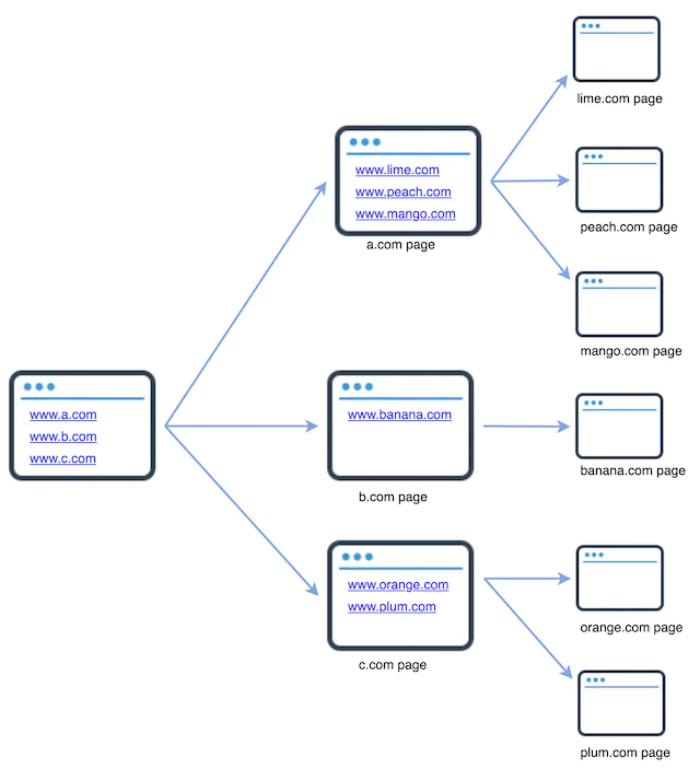


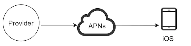
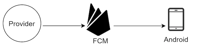
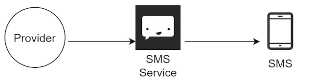
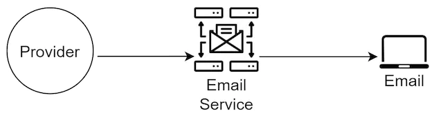
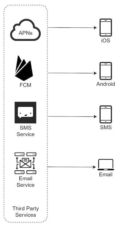
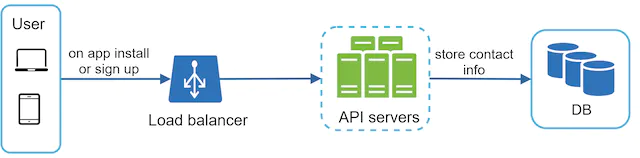
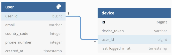
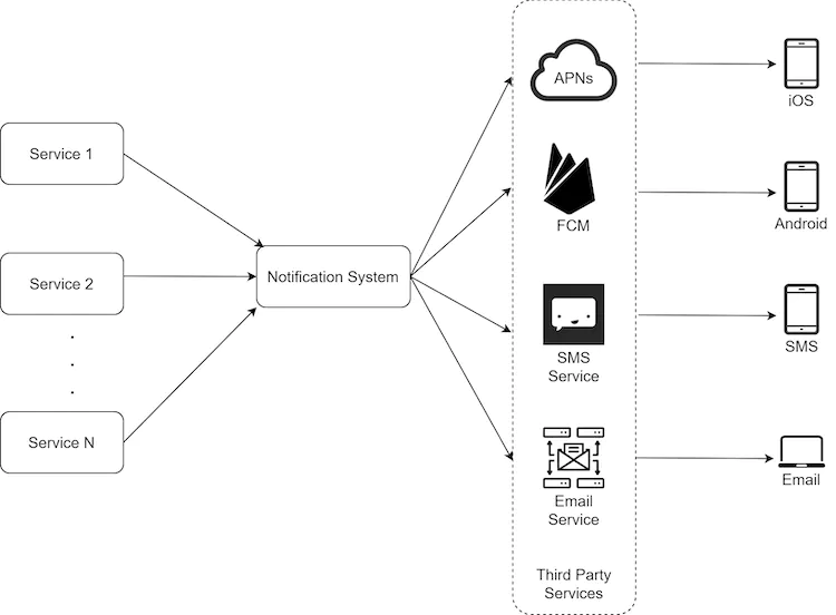
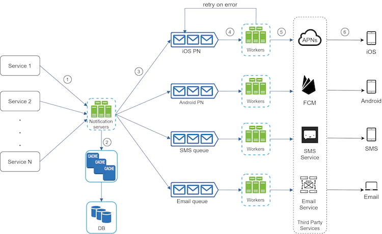

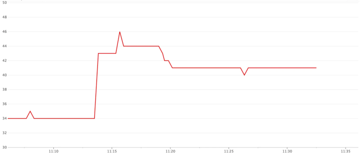

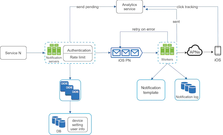
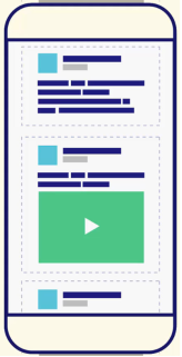
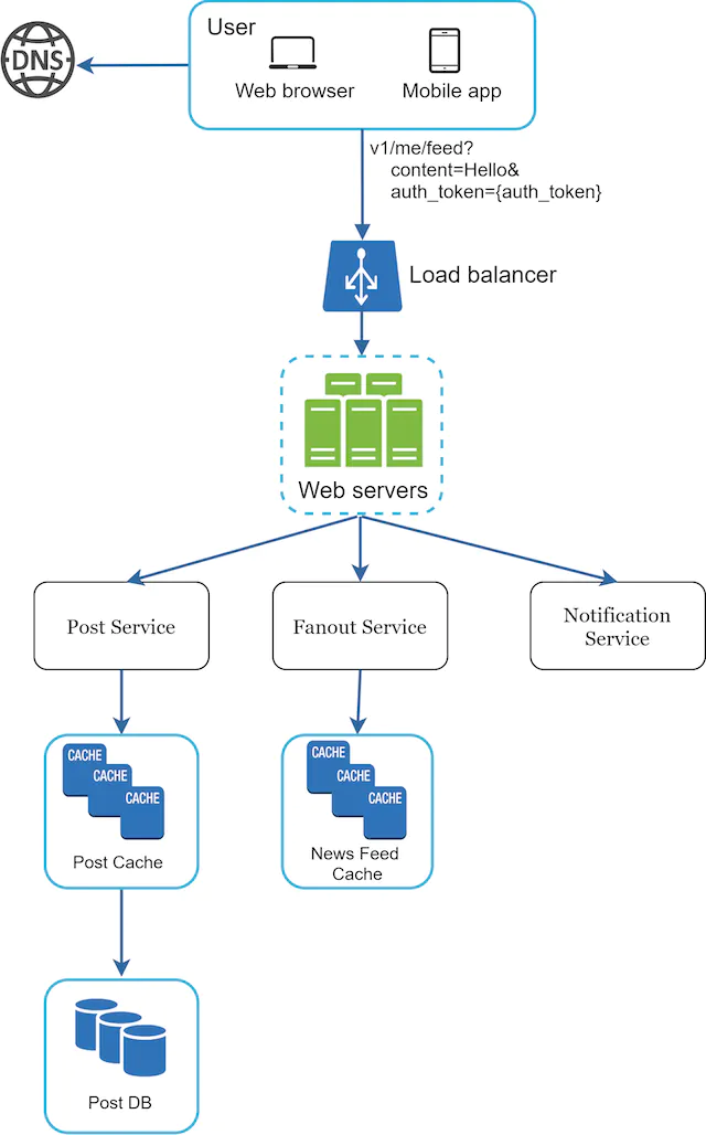
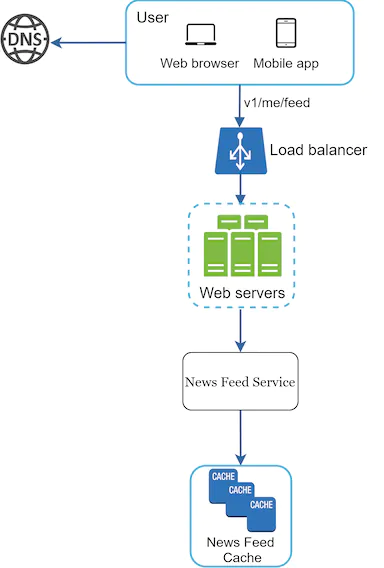
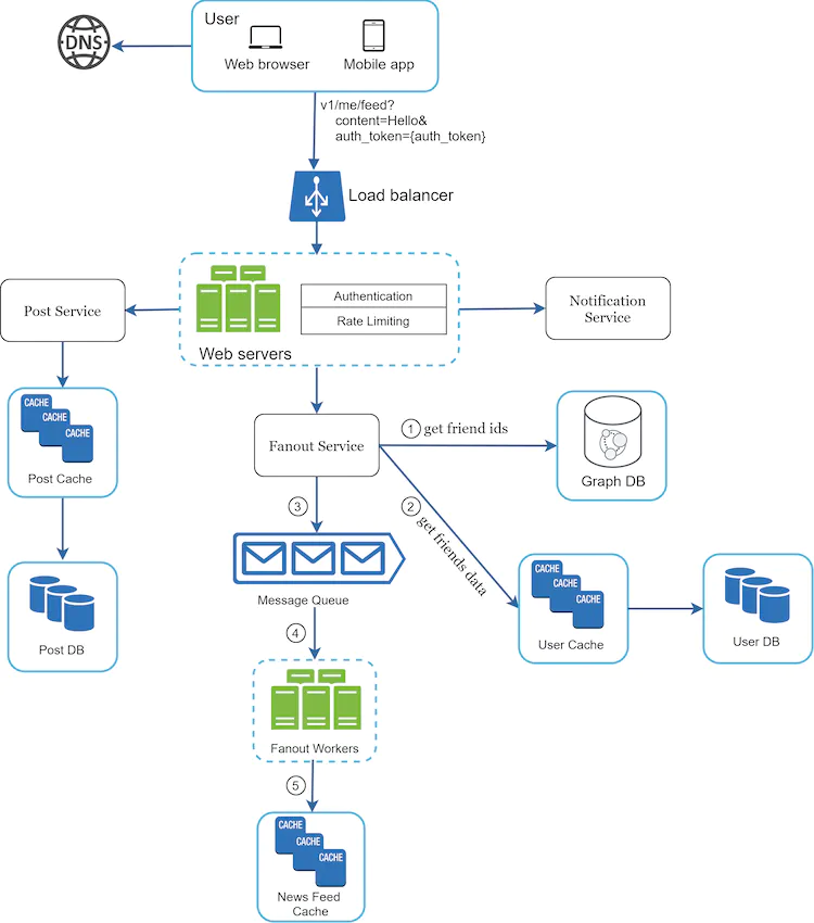

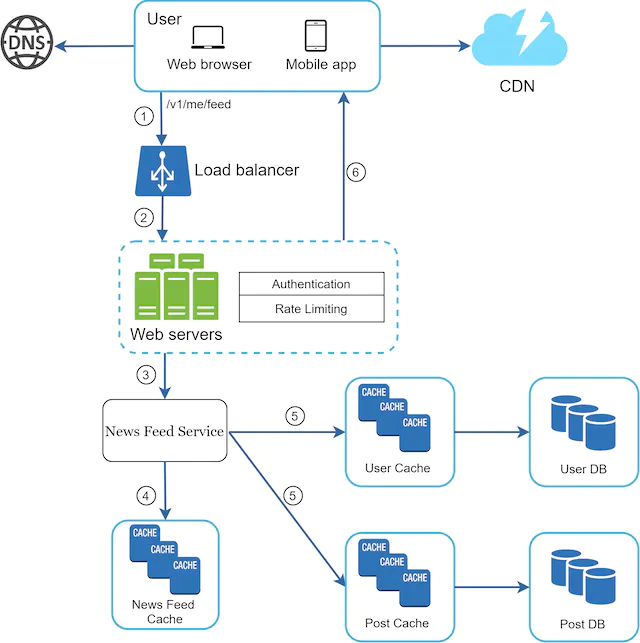

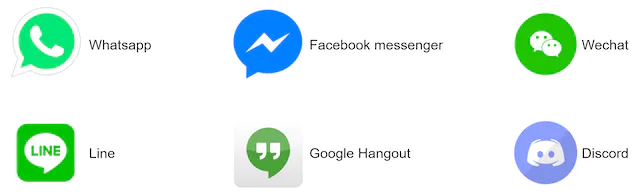



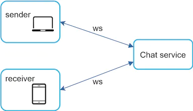
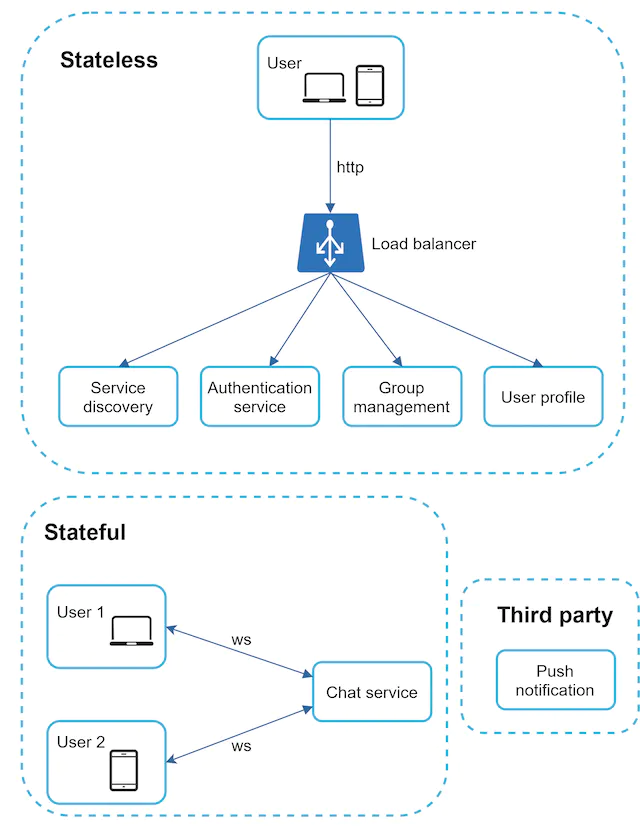
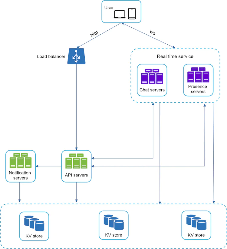
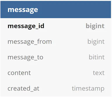
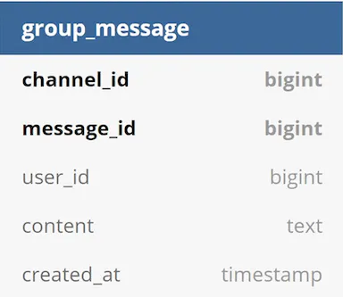
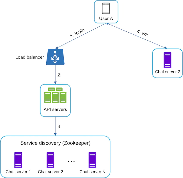
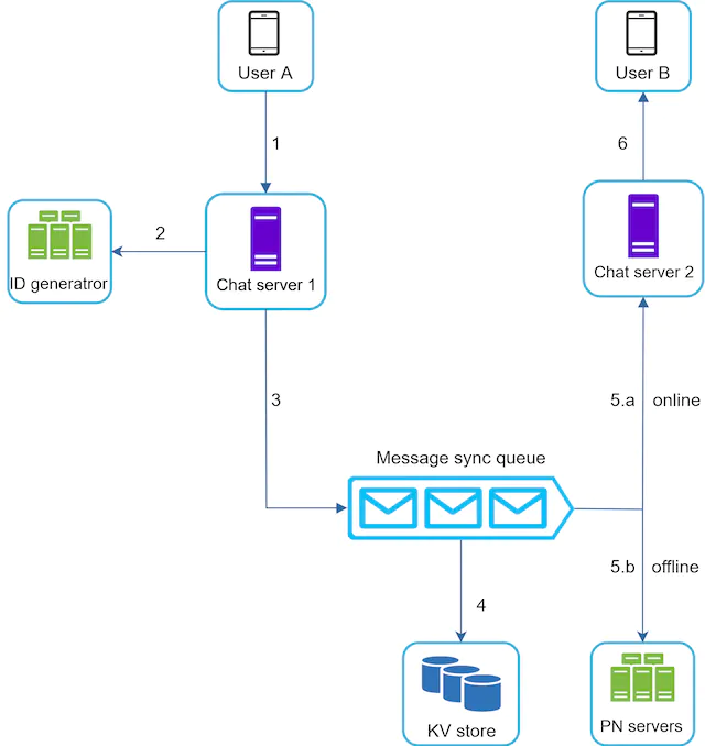
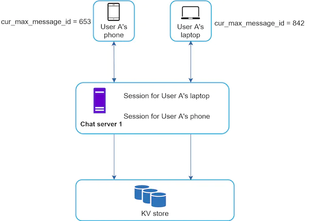
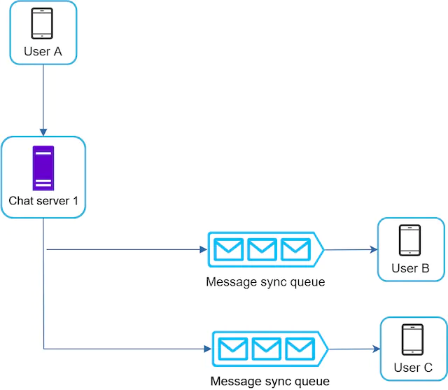
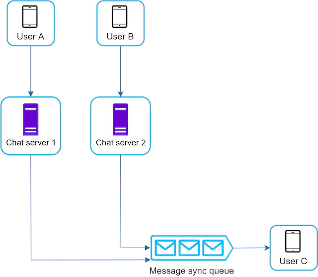
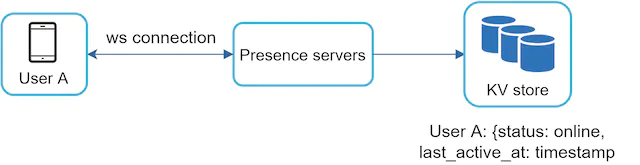
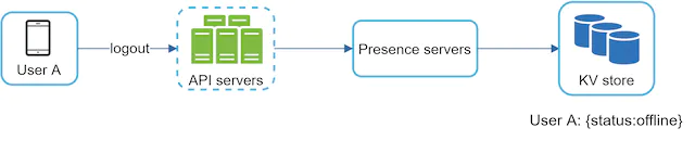

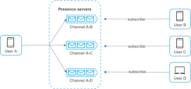


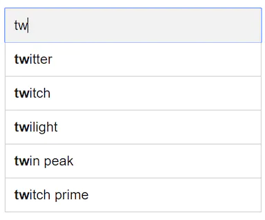
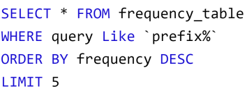


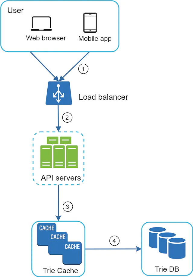
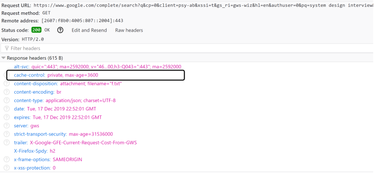

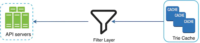

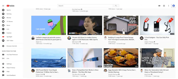

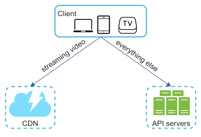
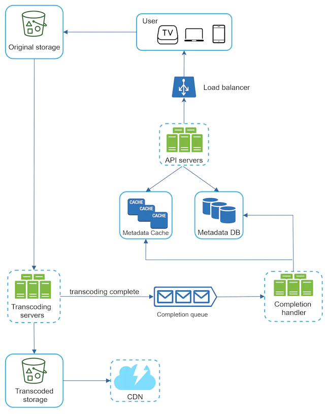
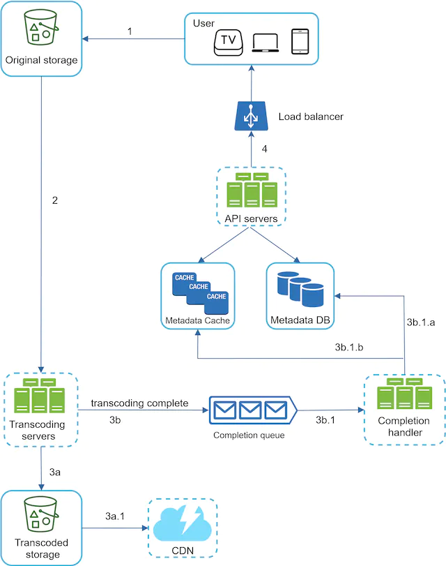
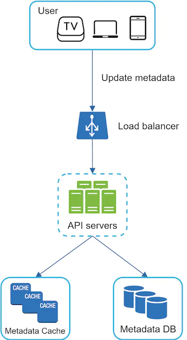
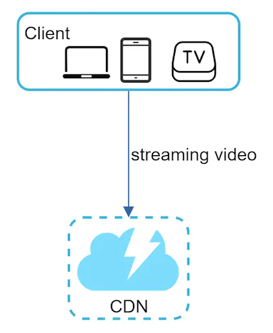


![Figure 13 (source: [9])](images/img_7e86589d29ba.webp)


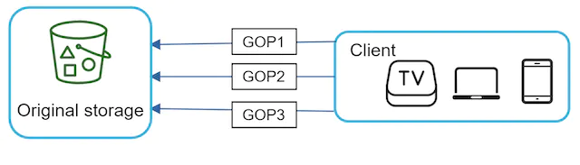


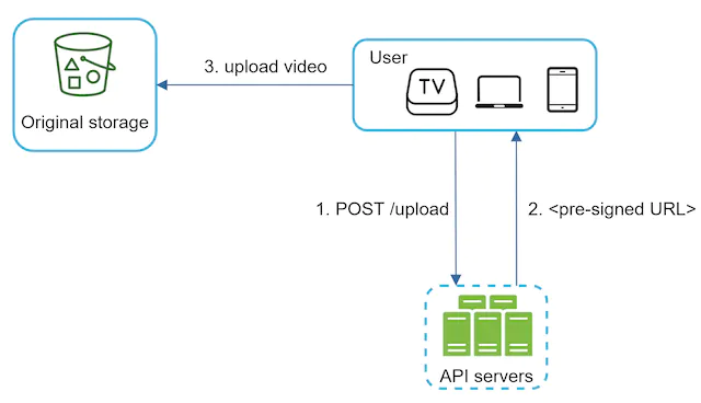
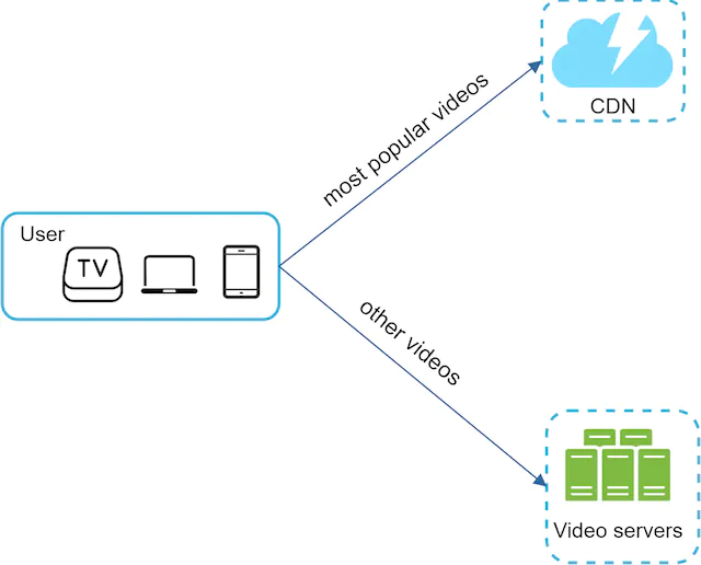
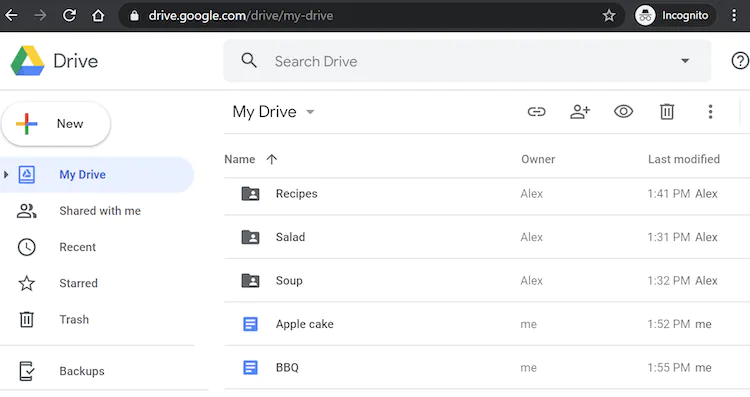
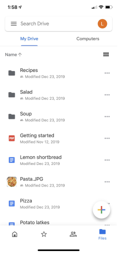



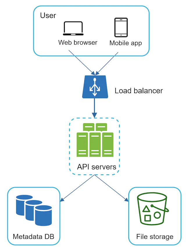

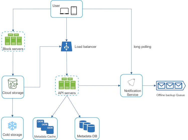
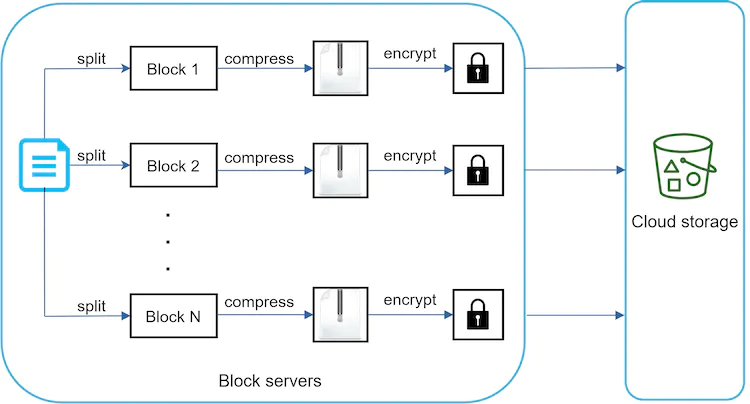

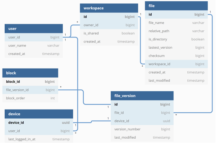


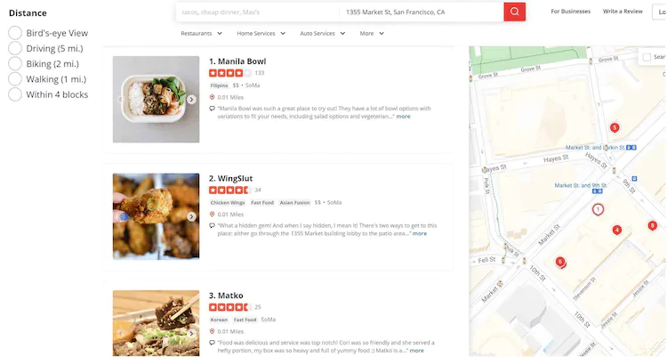
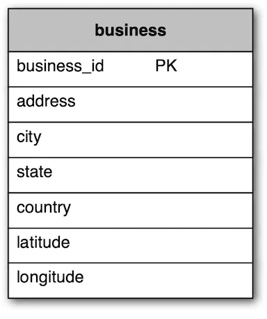
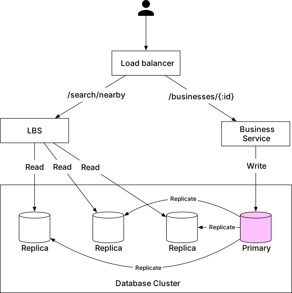
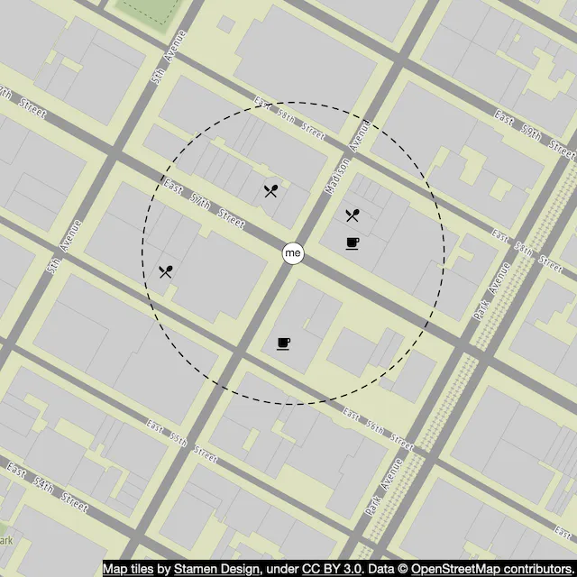

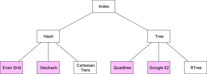
![Figure 6 Global map (source: [14])](images/img_444d3b604da2.webp)
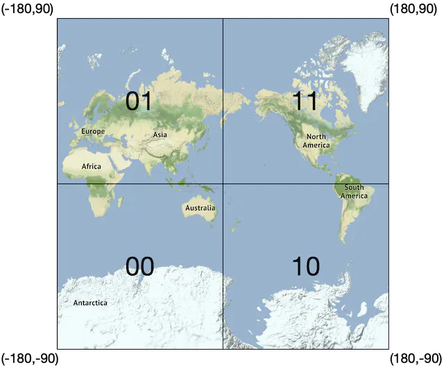
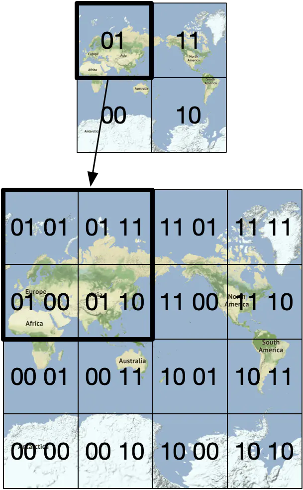
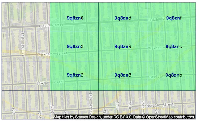
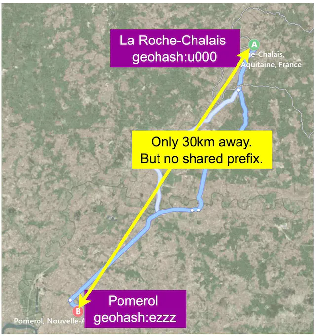
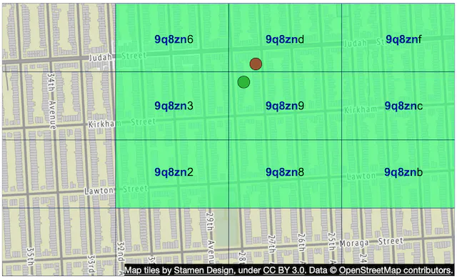
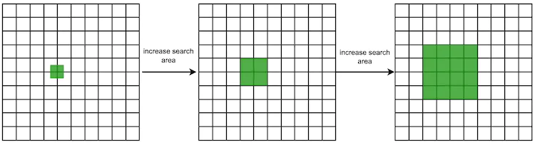
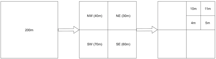
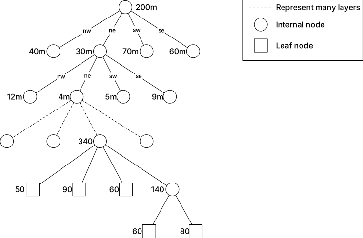
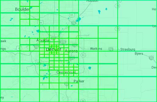
![Figure 16 Hilbert curve (source: [24])](images/img_17db92cfbd06.webp)
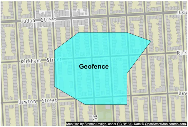
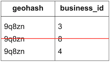
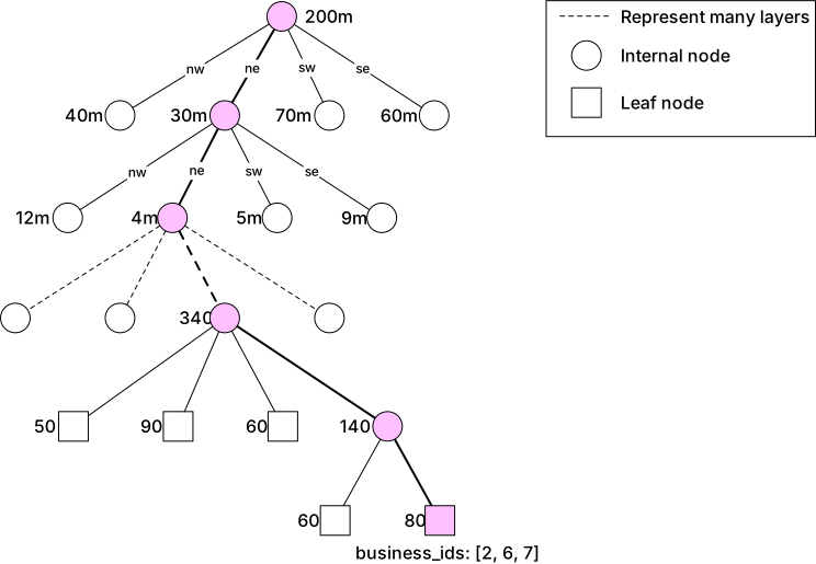
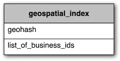
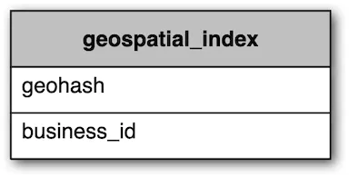
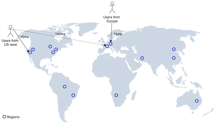
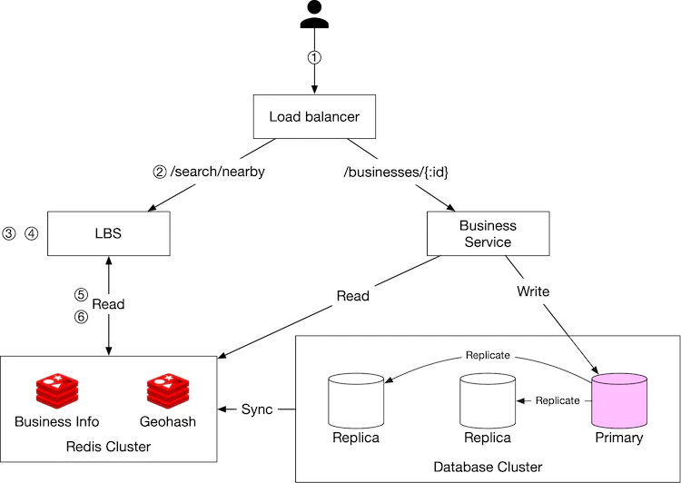
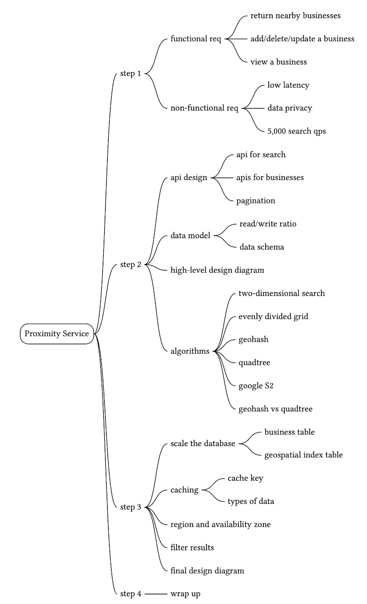
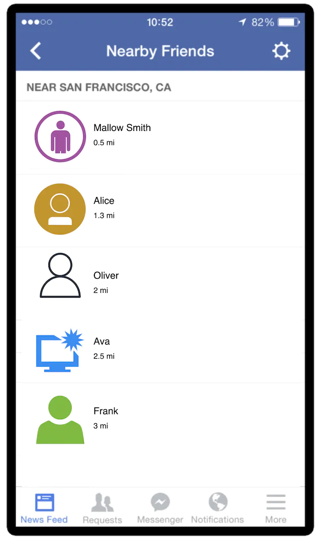
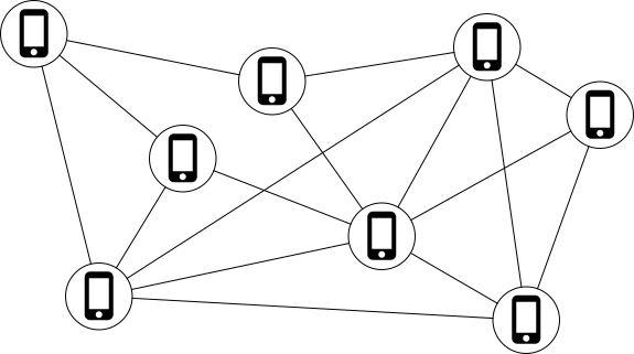
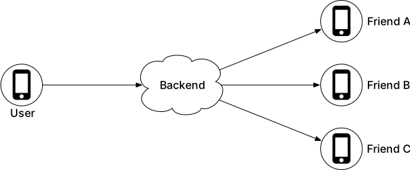
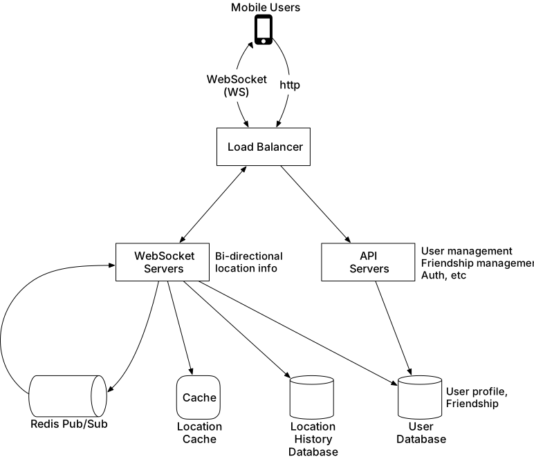
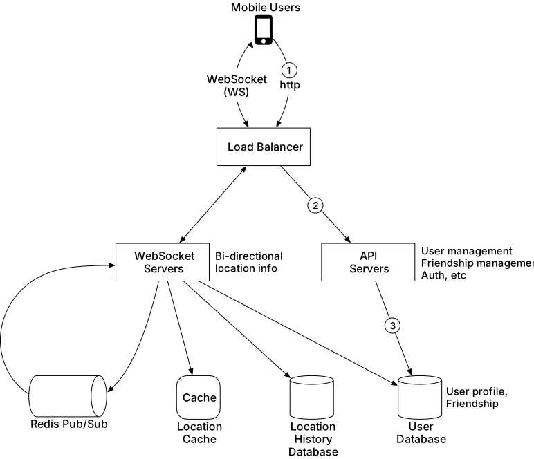
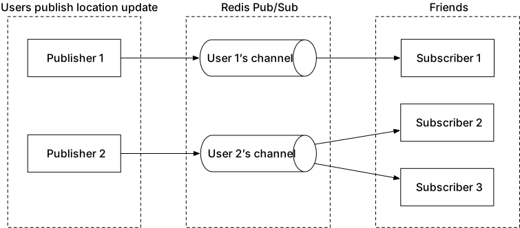
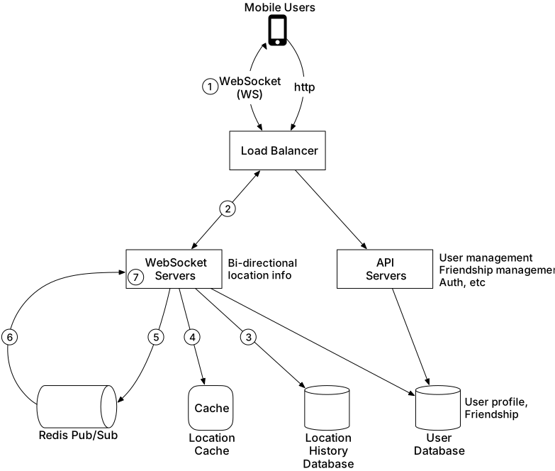
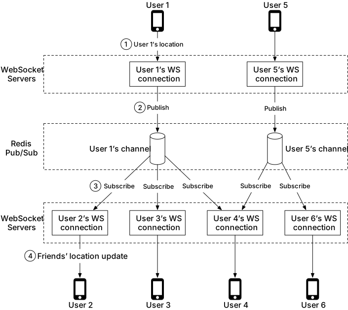
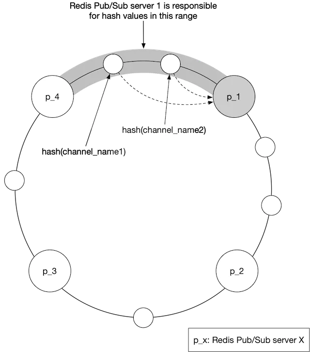
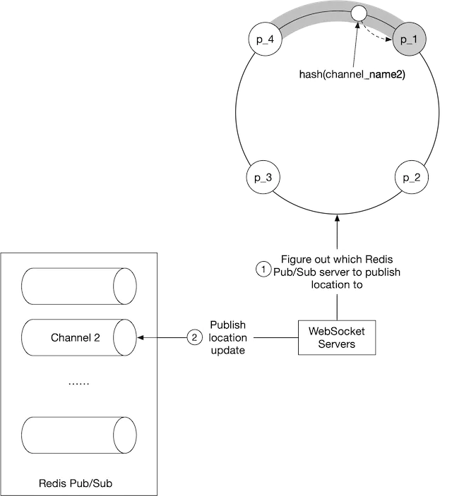
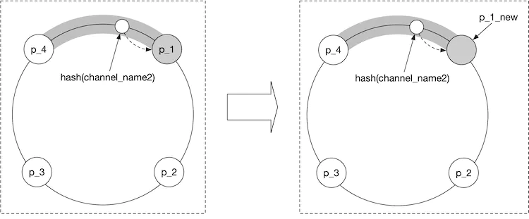
![Figure 12 Redis pub/sub channels (map source: [7])](images/img_7d7b4b0fccaa.svg)
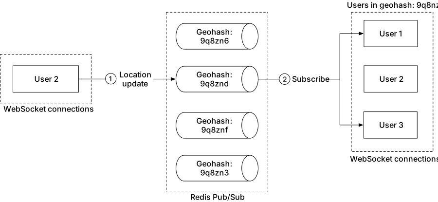
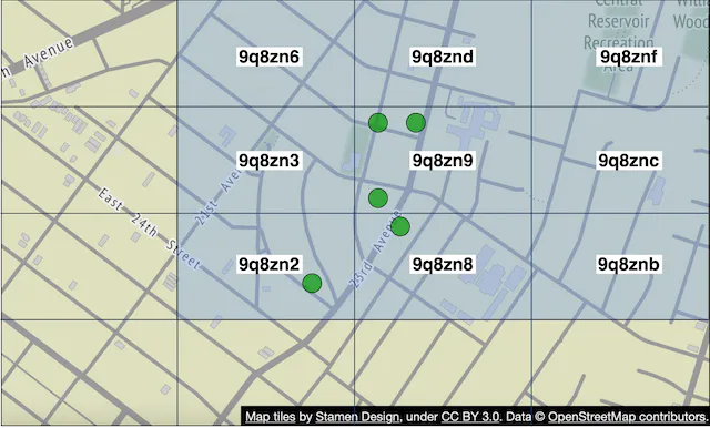
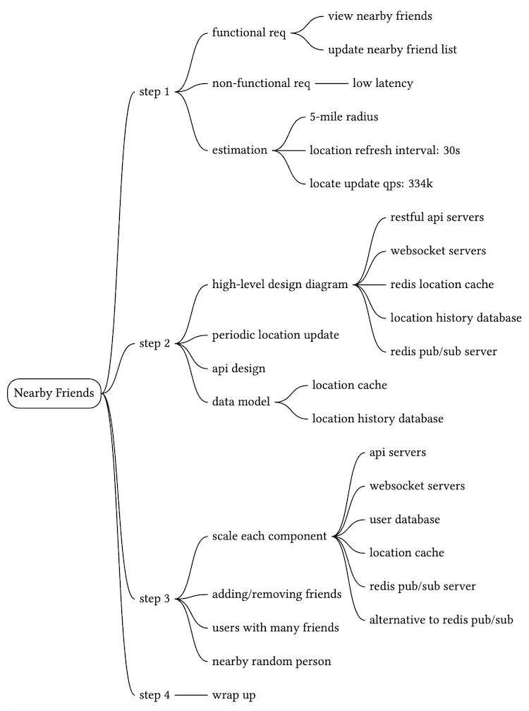
![Figure 1 Latitude and Longitude (source: [5])](images/img_1e789a5ed2a4.webp)
![Figure 2 Map projections (source: Wikipedia [6] [7] [8] [9])](images/img_887098fc963f.webp)
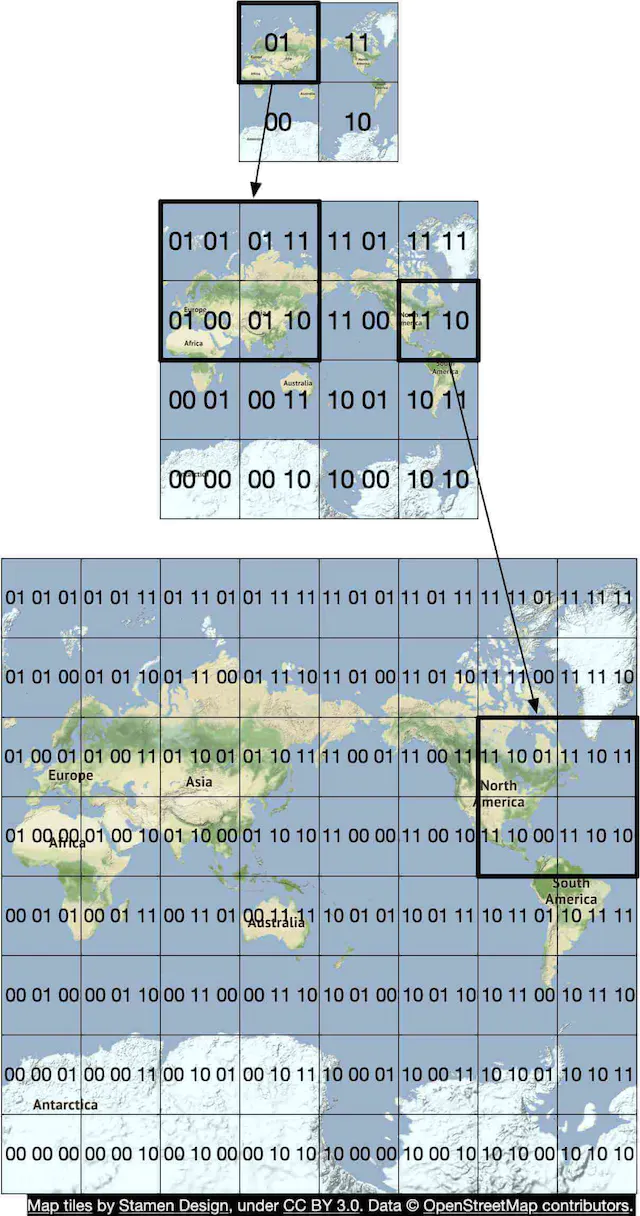
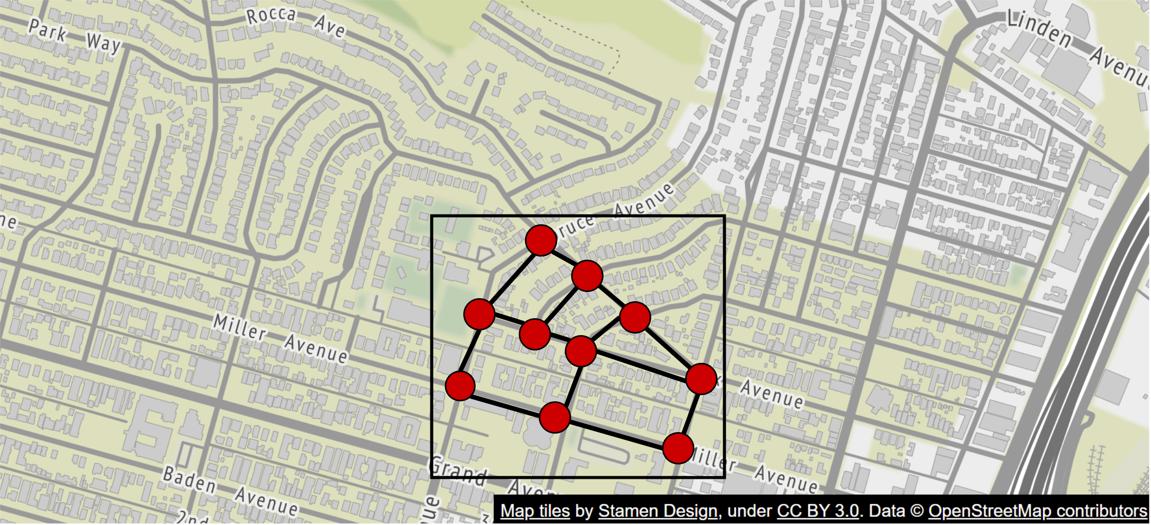

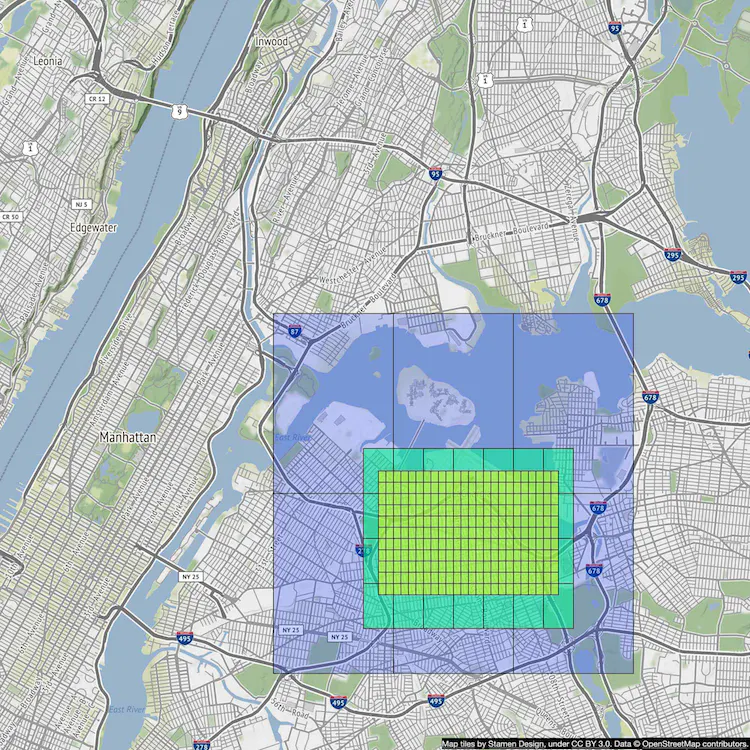
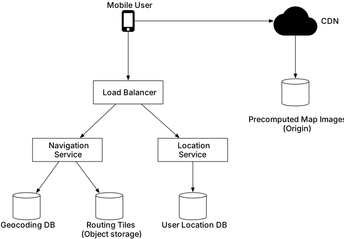
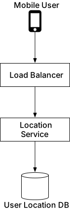
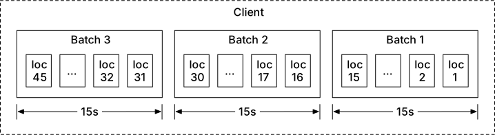
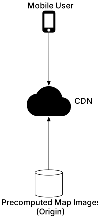
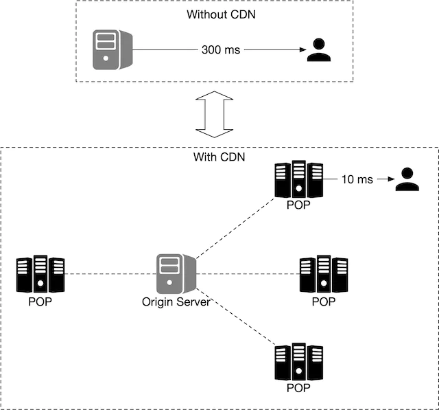
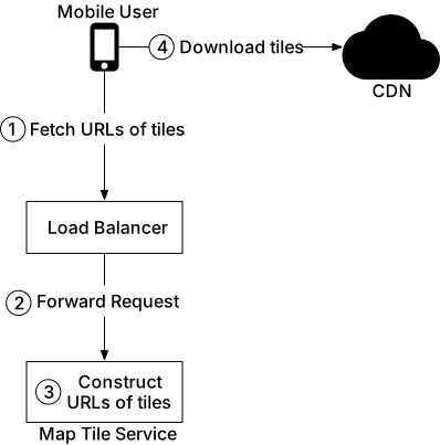
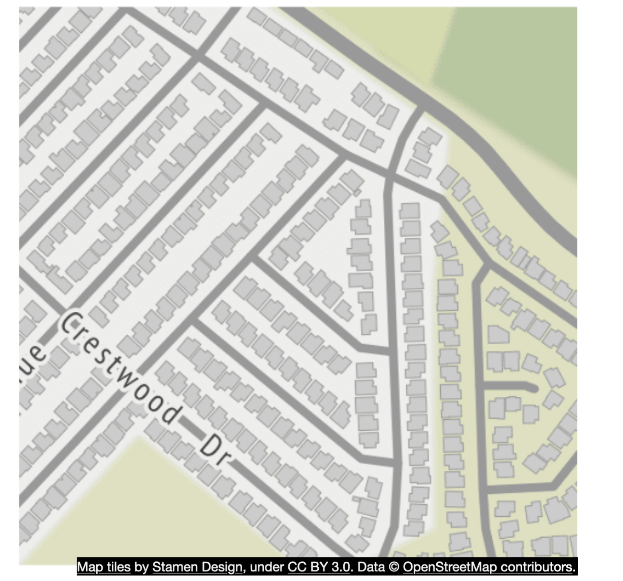
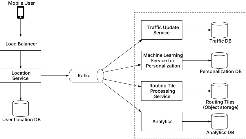
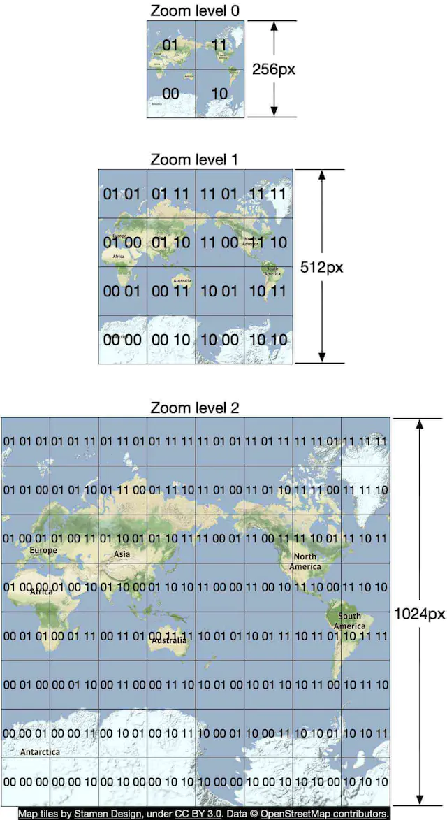
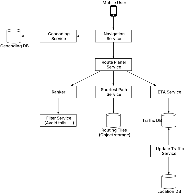
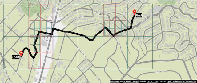
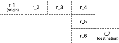
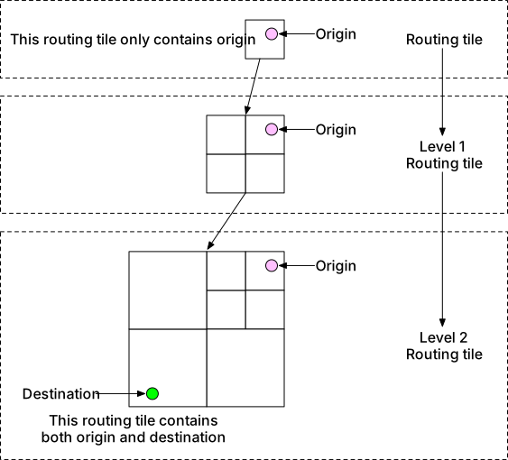
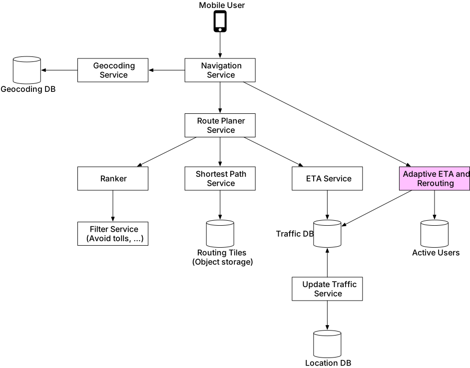
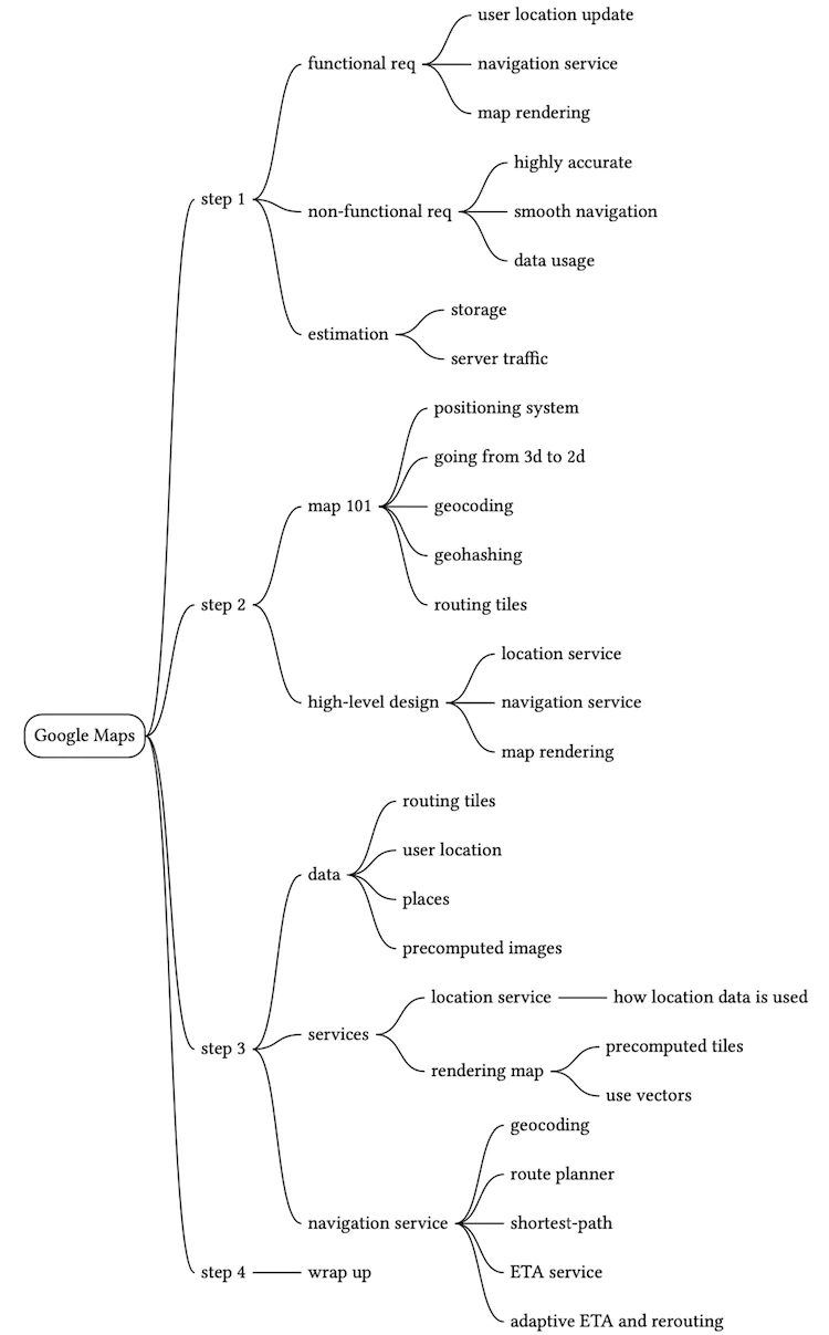
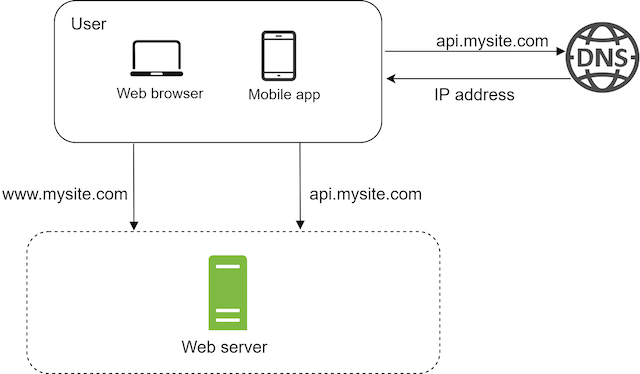
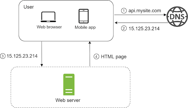
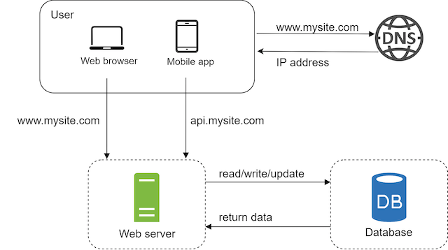
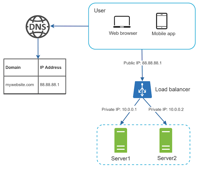

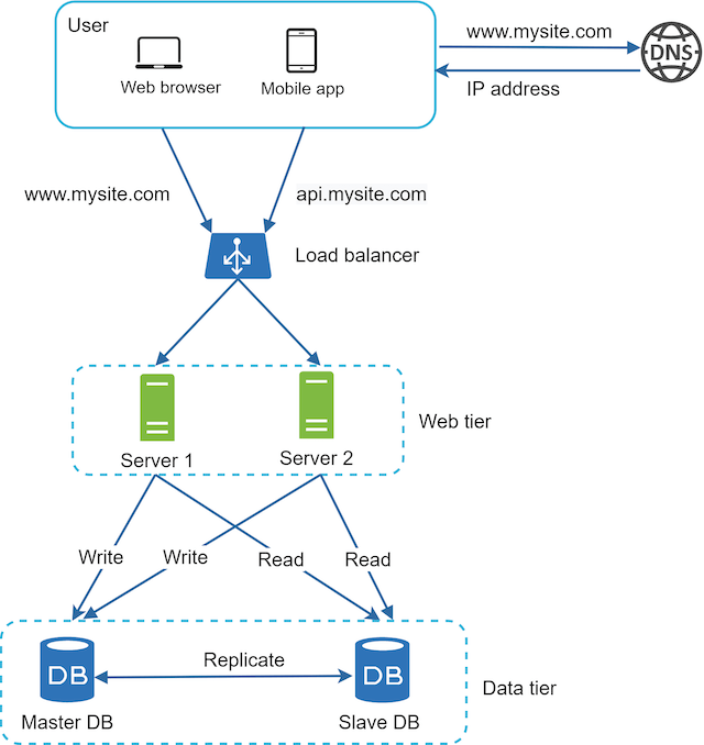


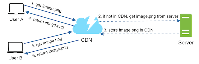
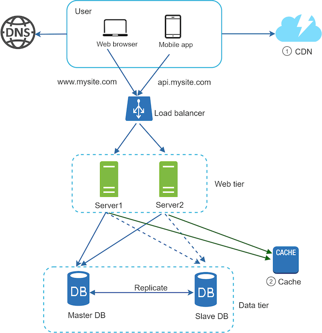
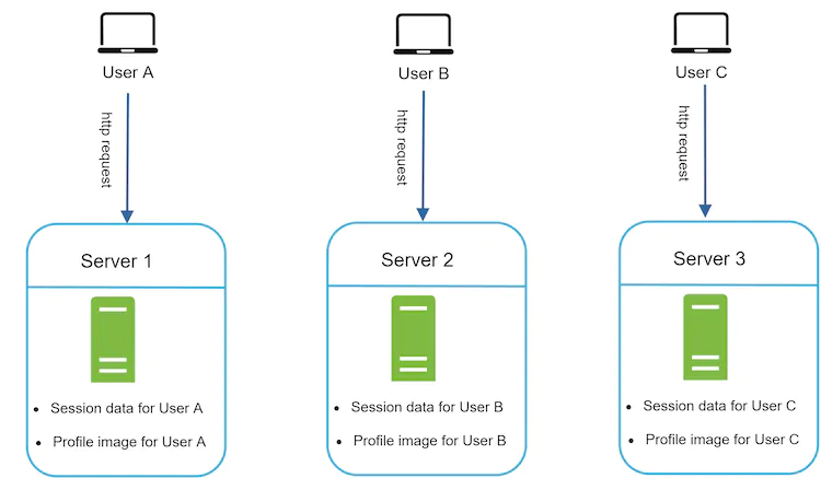
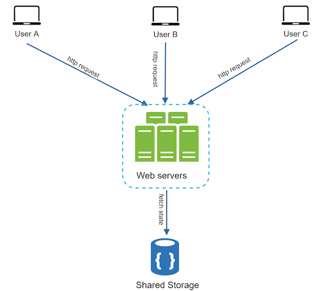
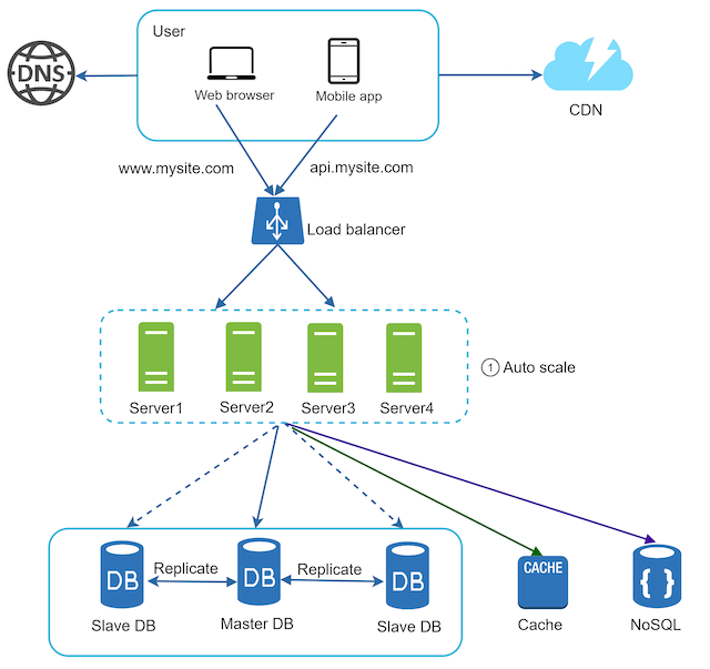
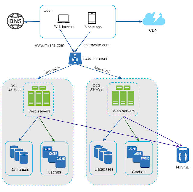
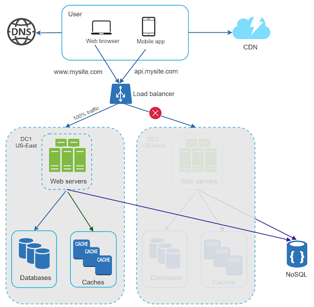


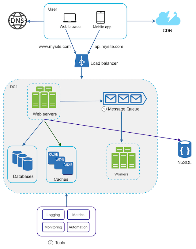


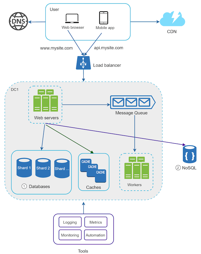

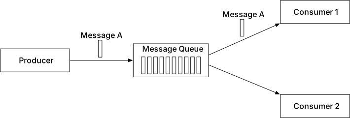
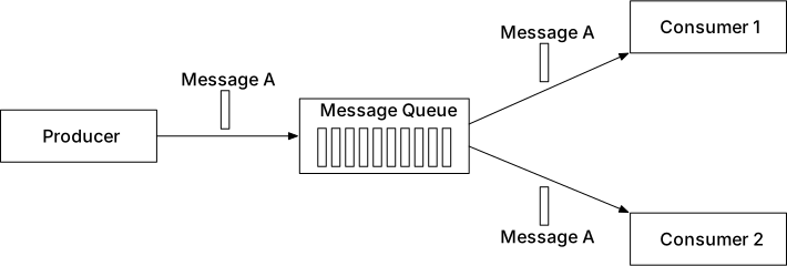


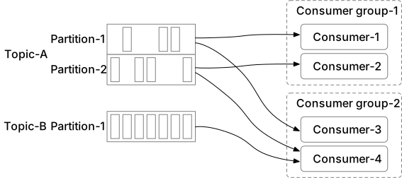
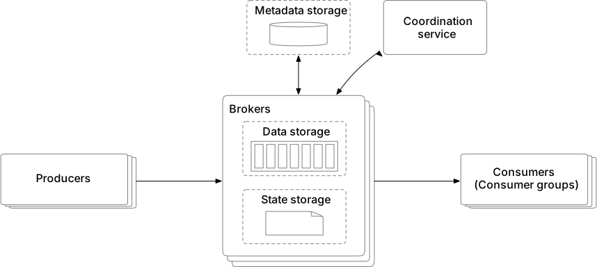
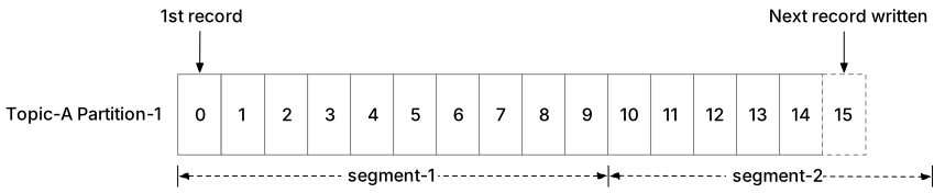
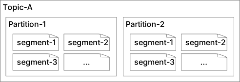
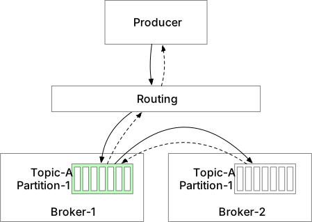
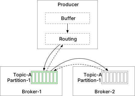

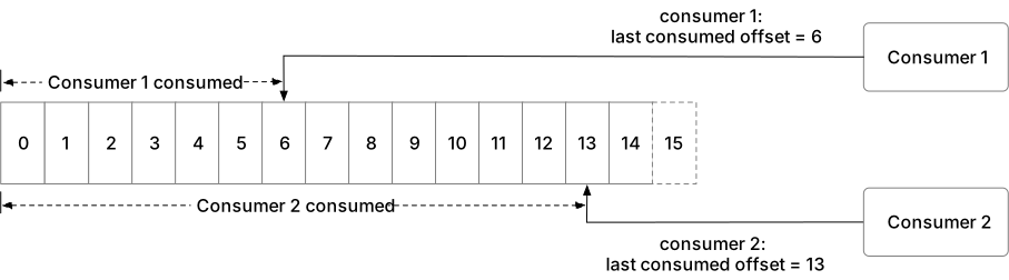
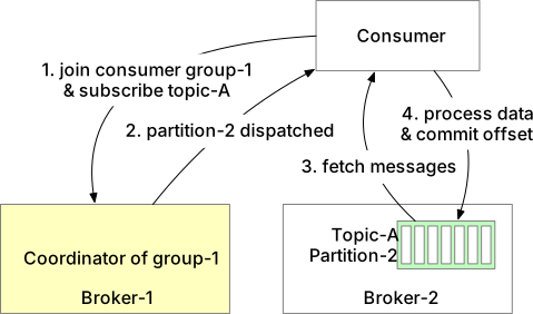
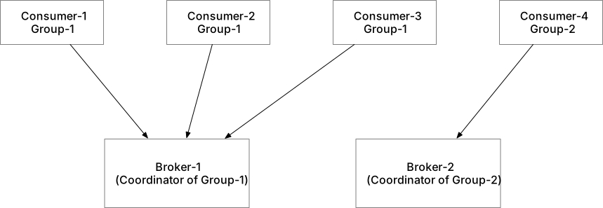
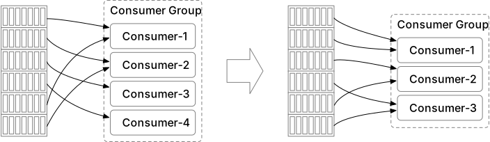
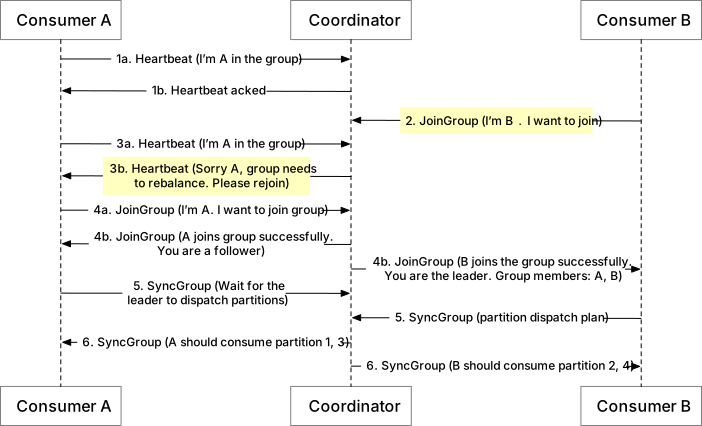
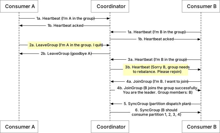
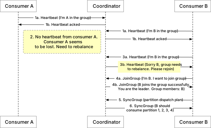
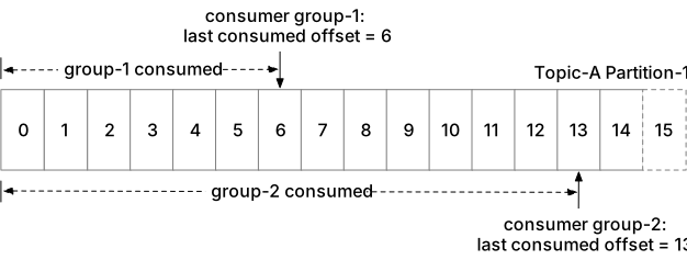
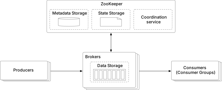
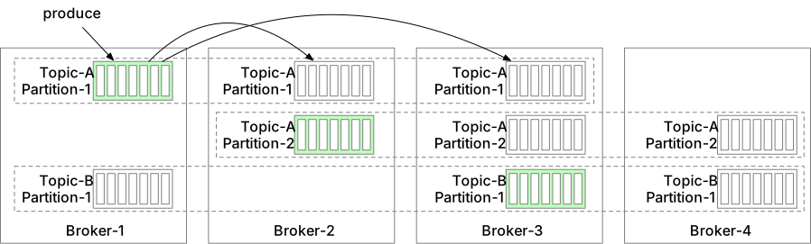
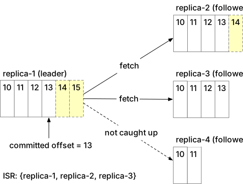
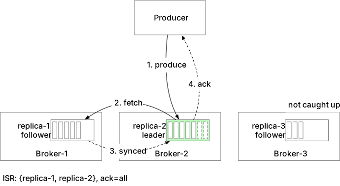
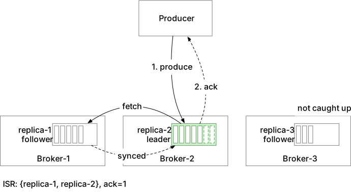
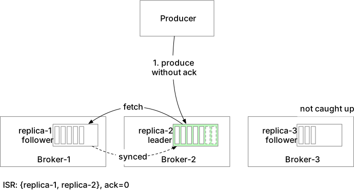
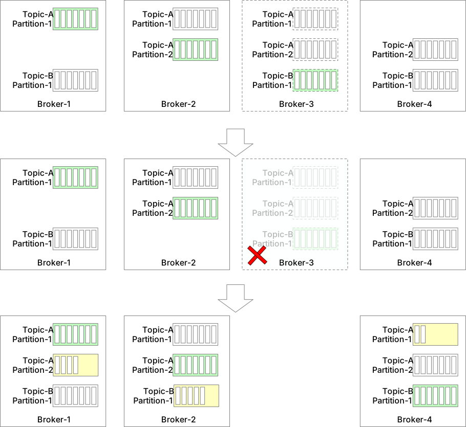
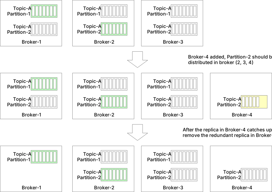
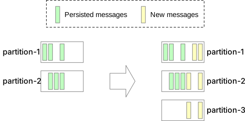
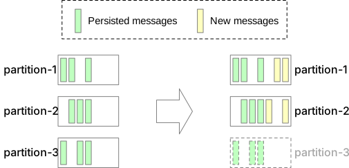




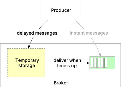
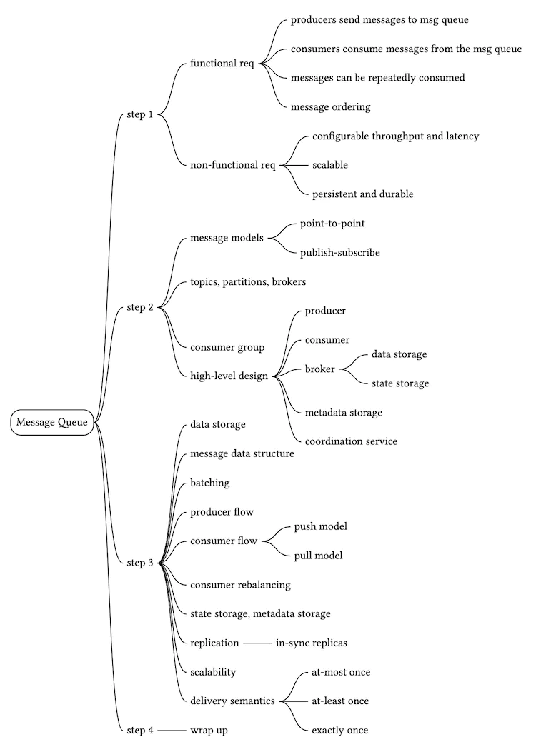
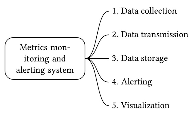


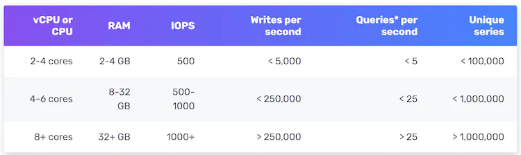
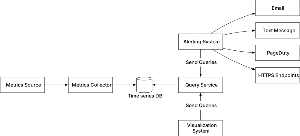
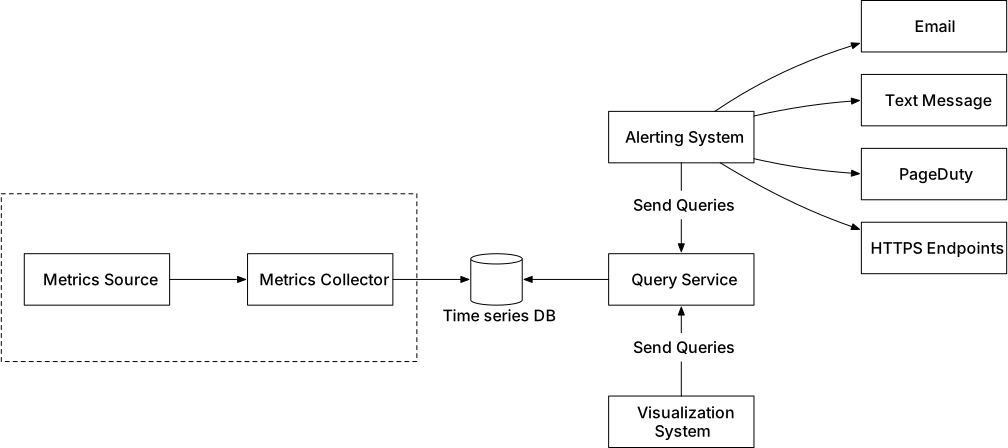
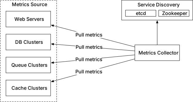
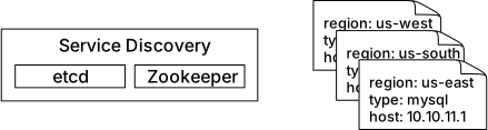
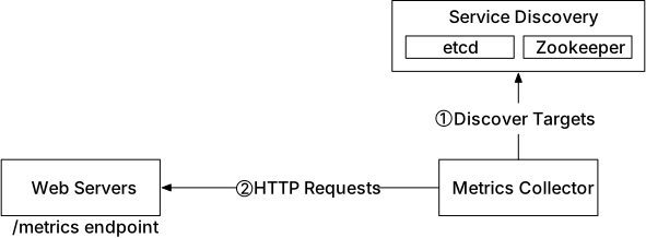
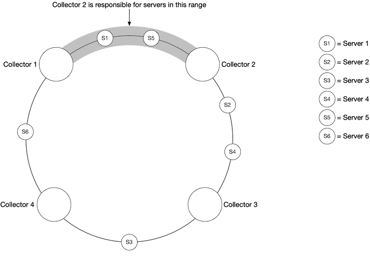
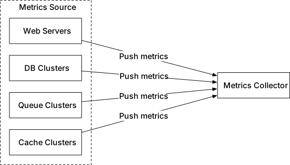
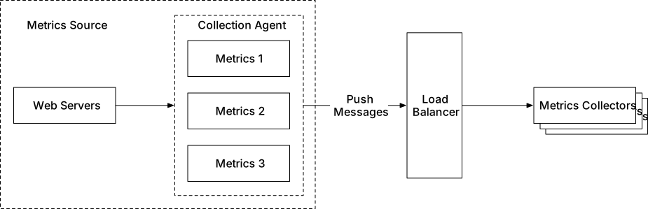
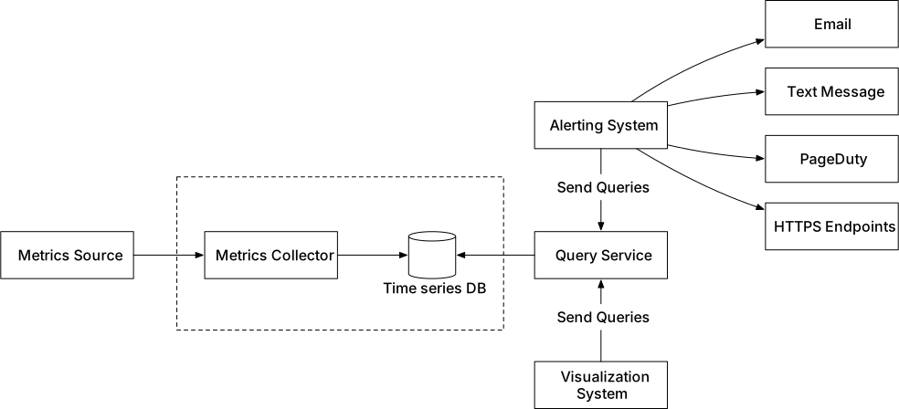
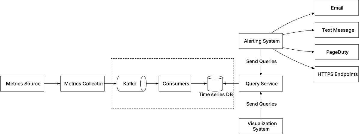
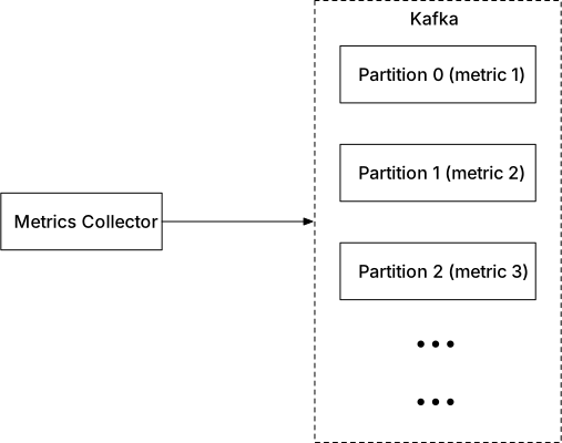
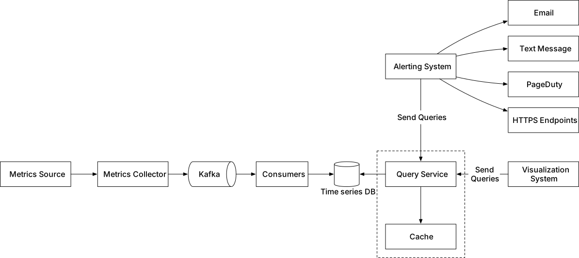
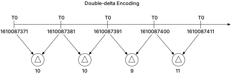
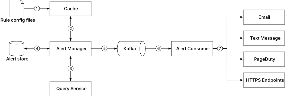
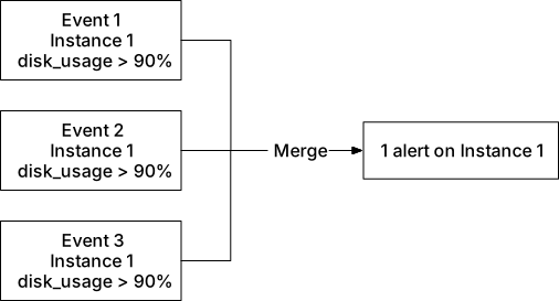
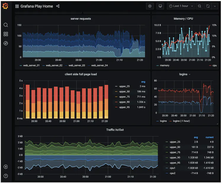
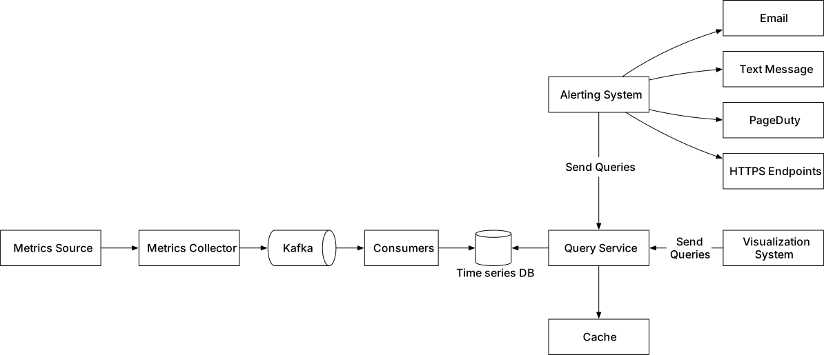
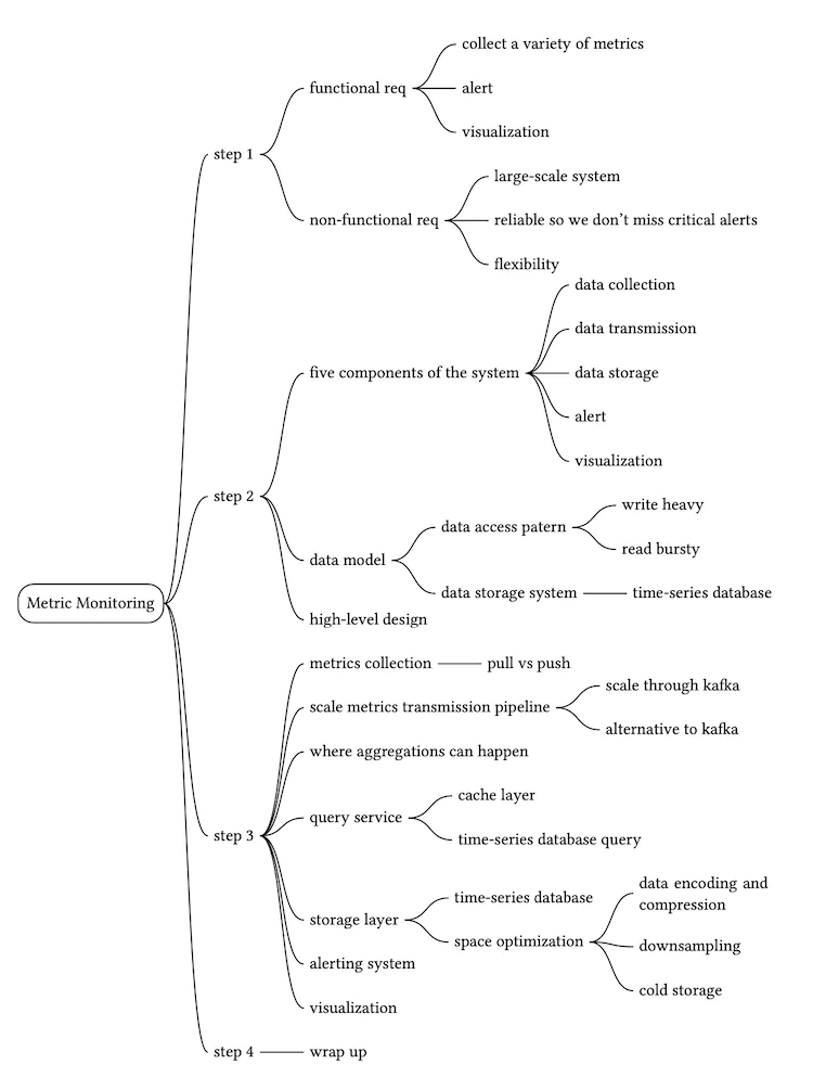


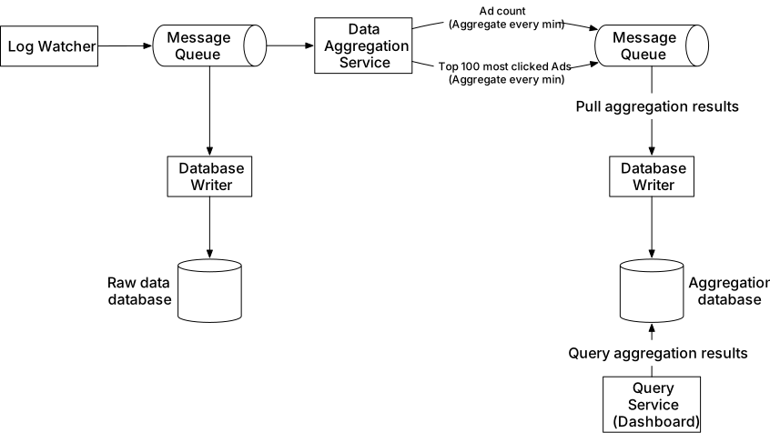
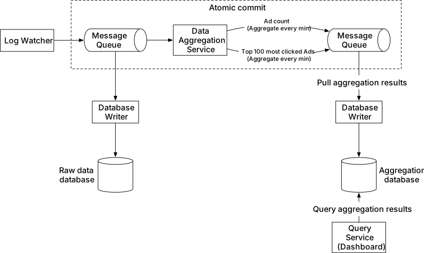
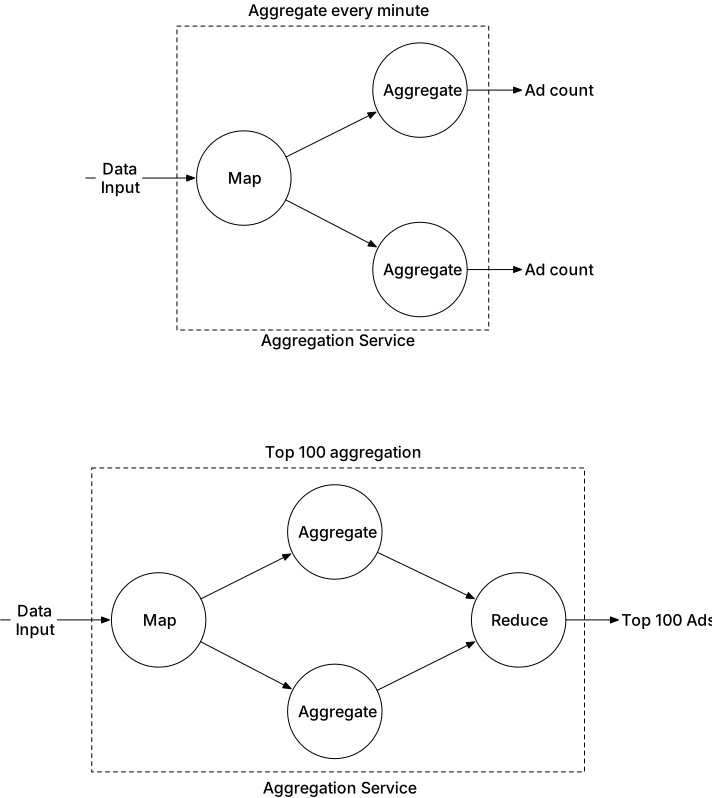
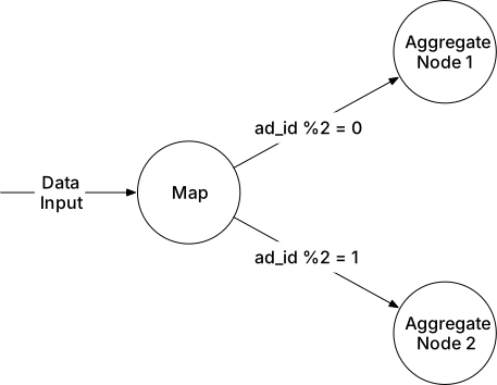
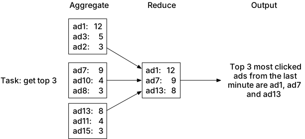
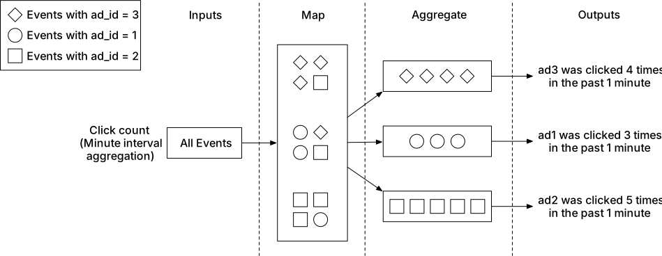
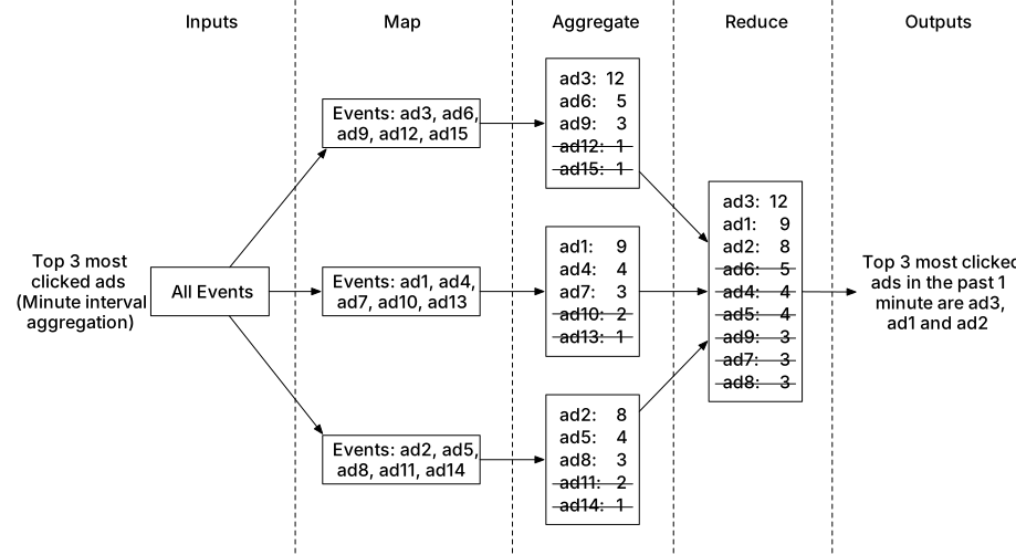

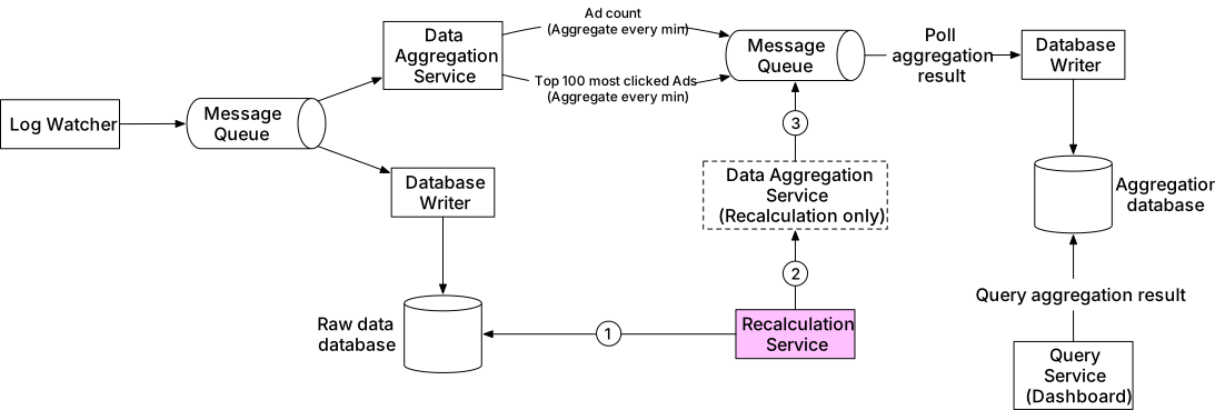
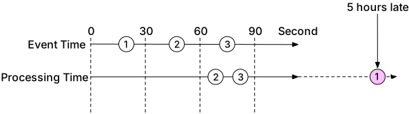
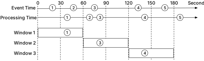
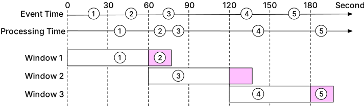
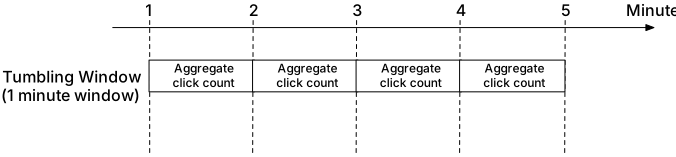
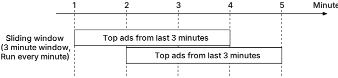


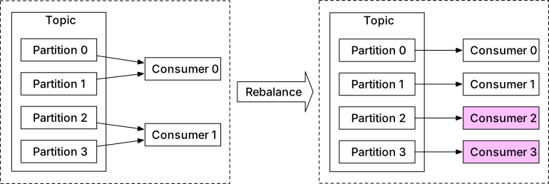
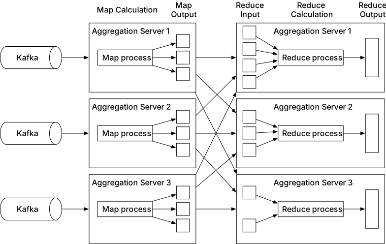
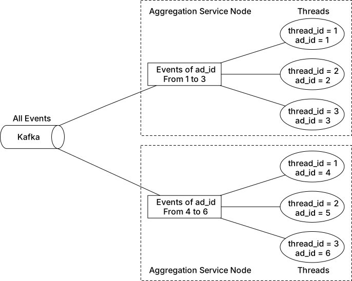
![Figure 24 Virtual nodes [22]](images/img_7b93b9884abd.webp)
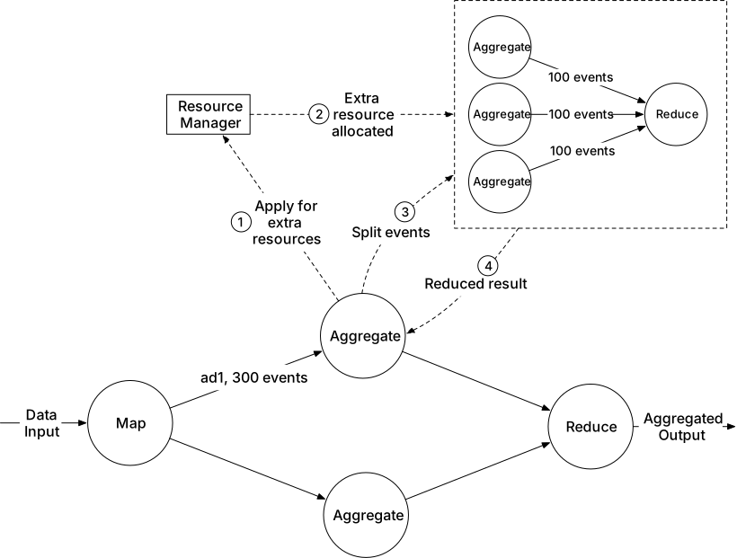
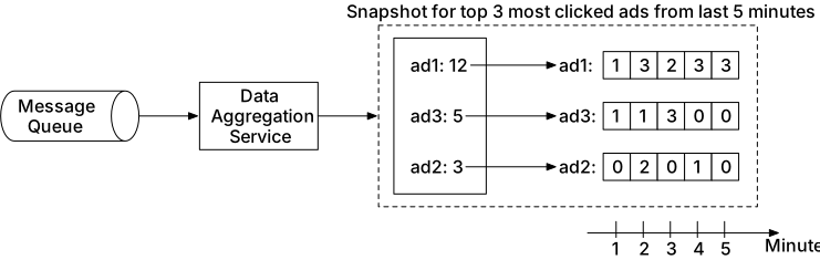
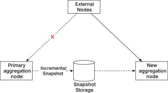
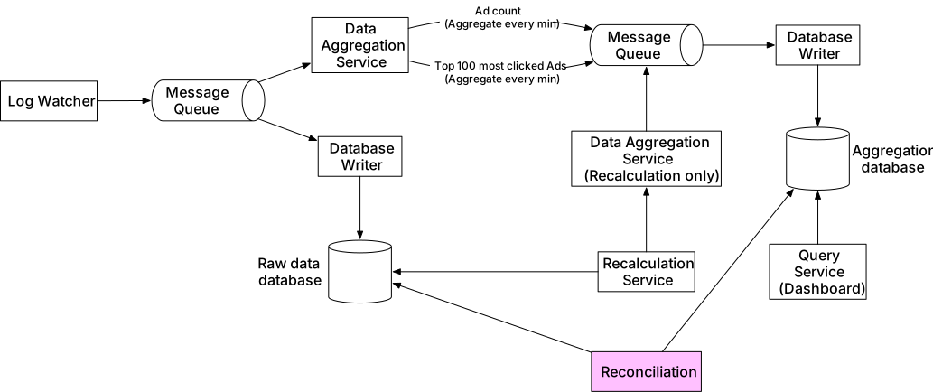
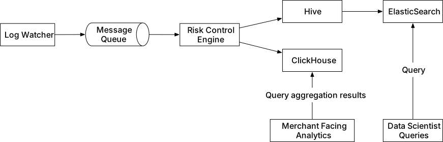
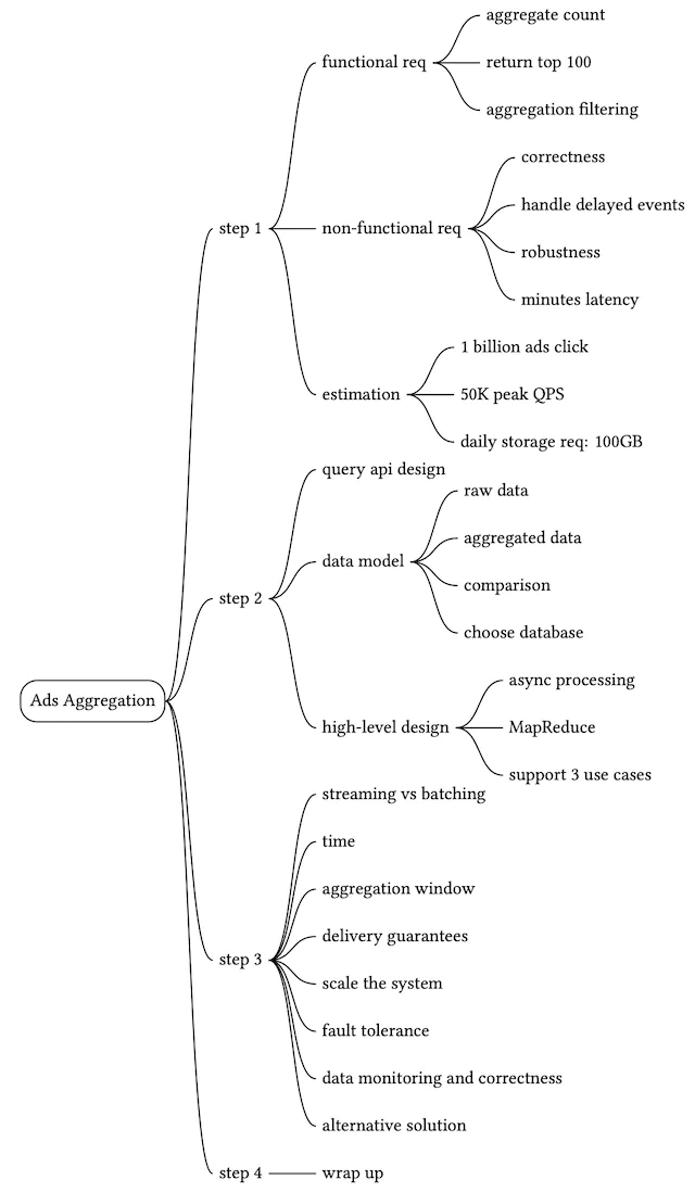
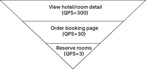
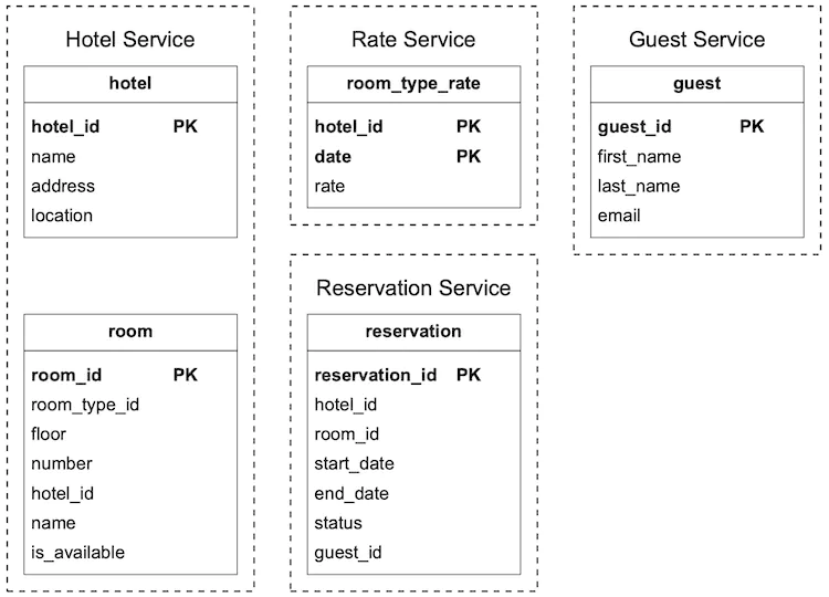
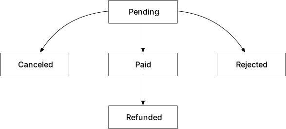
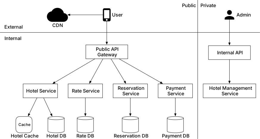
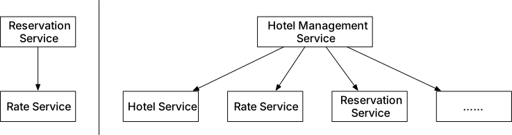
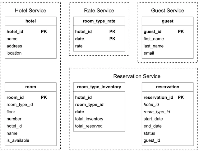
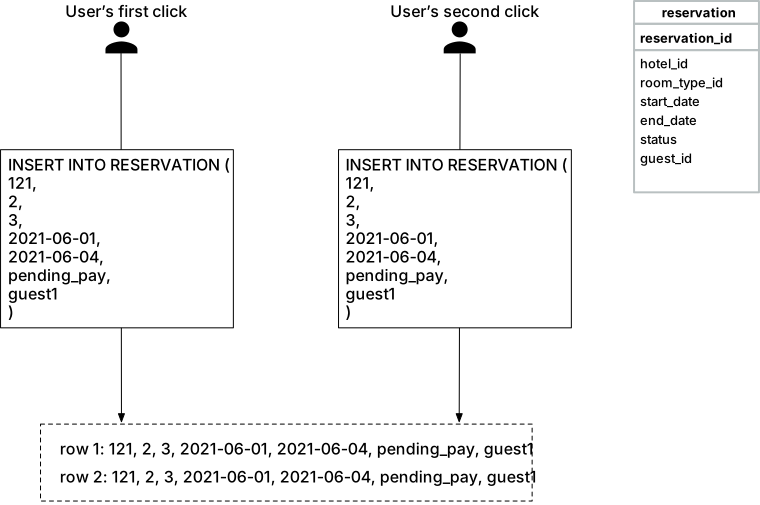
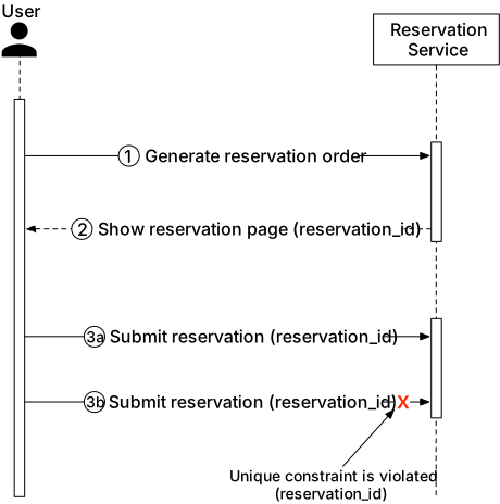
![Figure 9 Confirmation page (Source: [4])](images/img_f4bebf3b1ab4.webp)
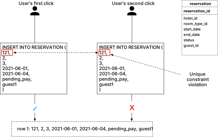
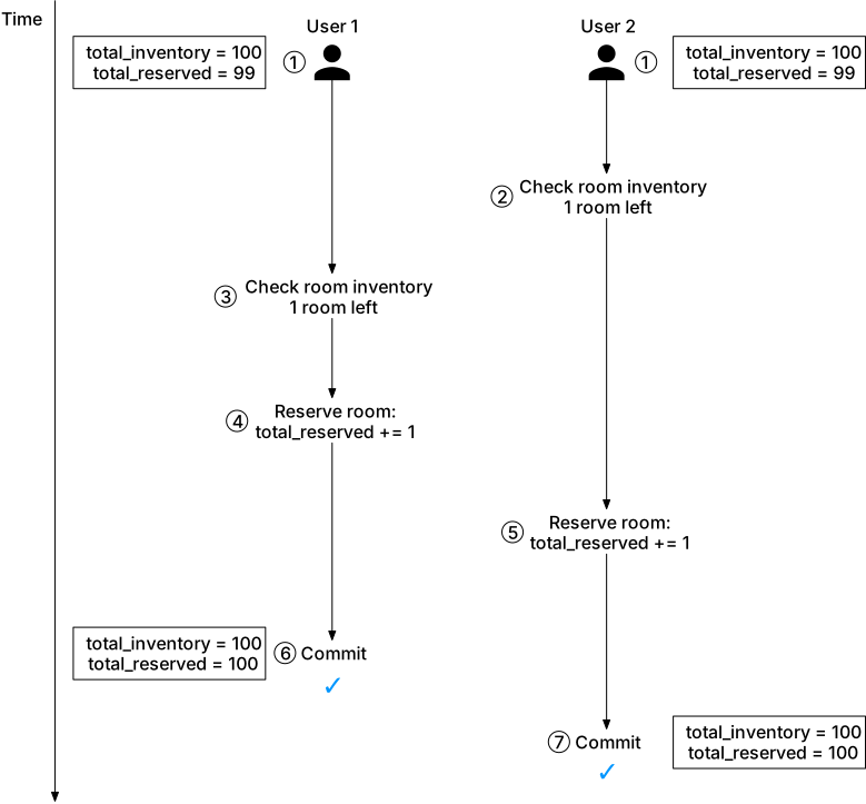
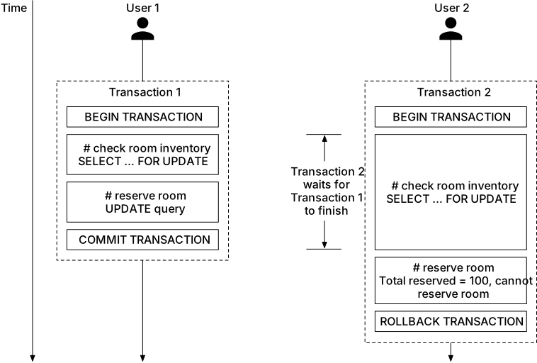
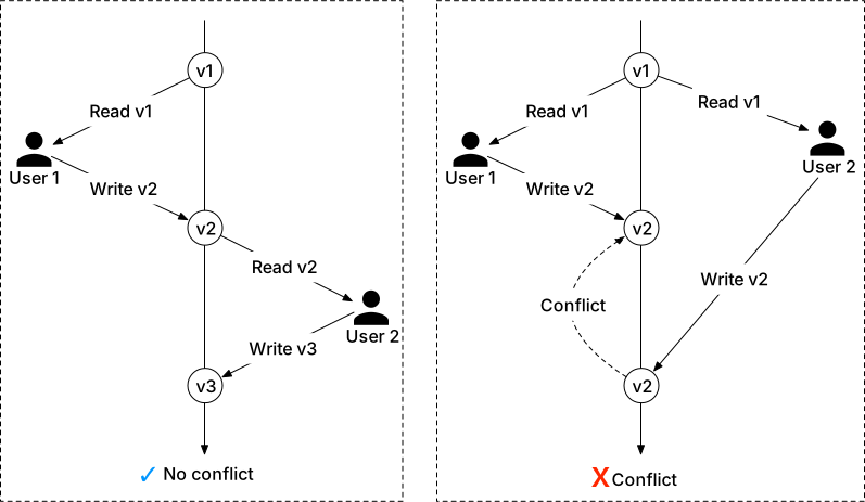
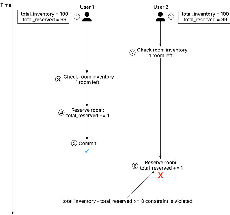
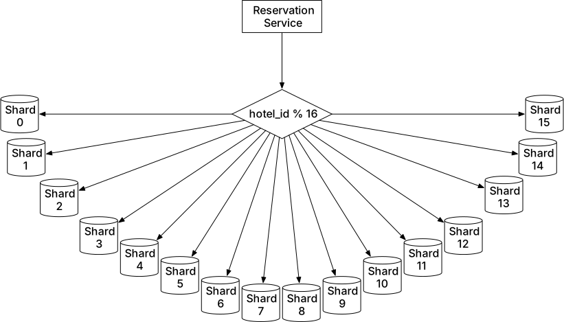
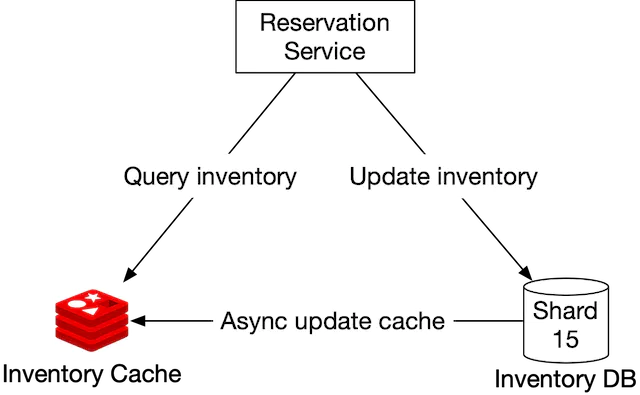
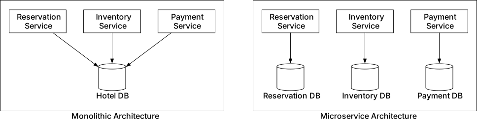
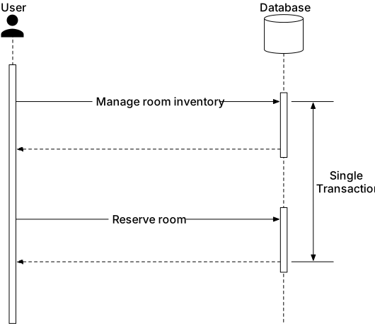
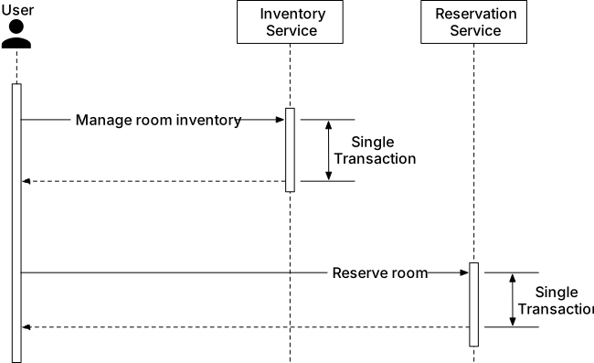
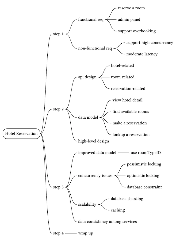

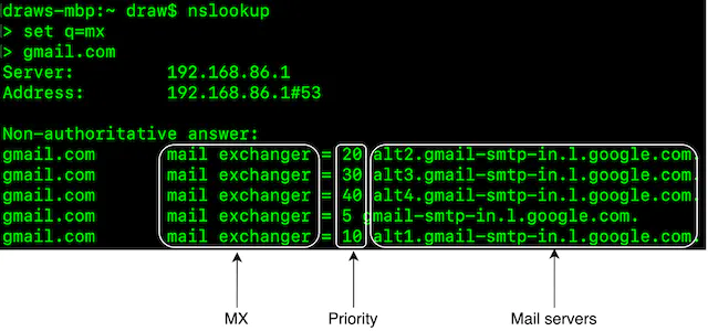
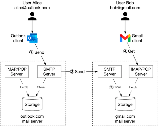

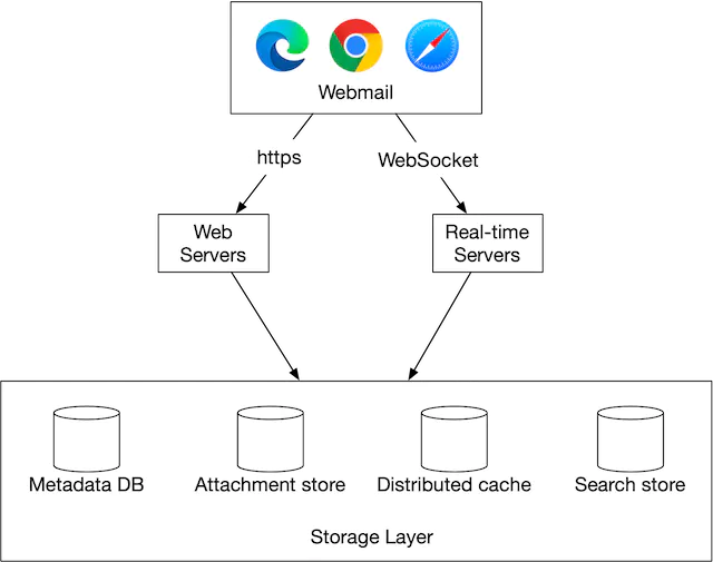
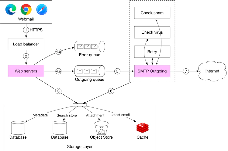
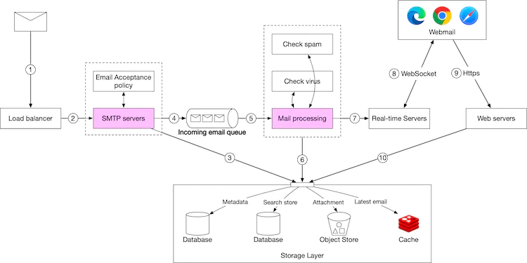
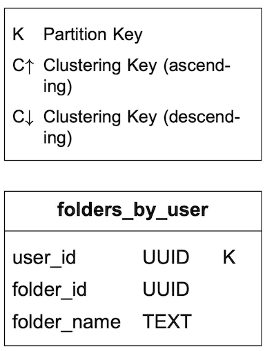
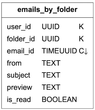
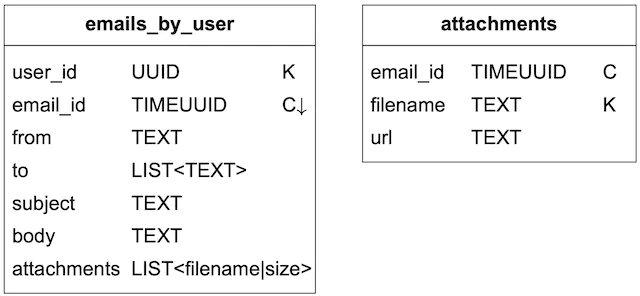
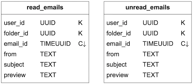
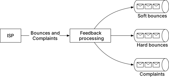
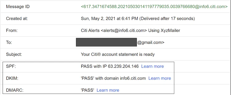
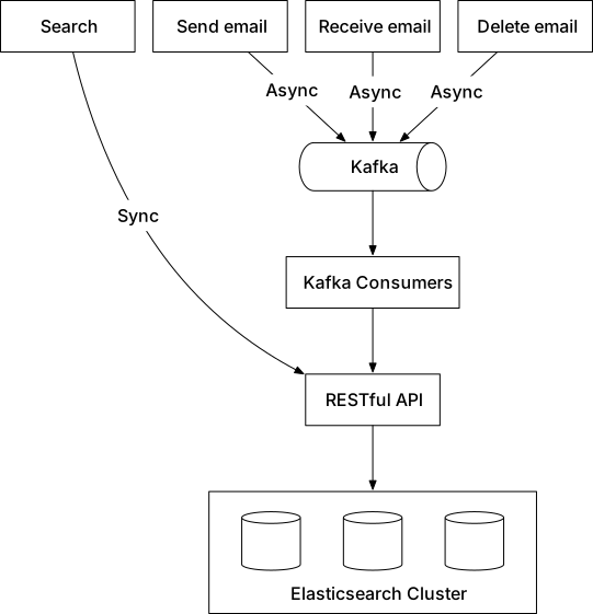
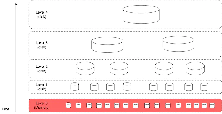
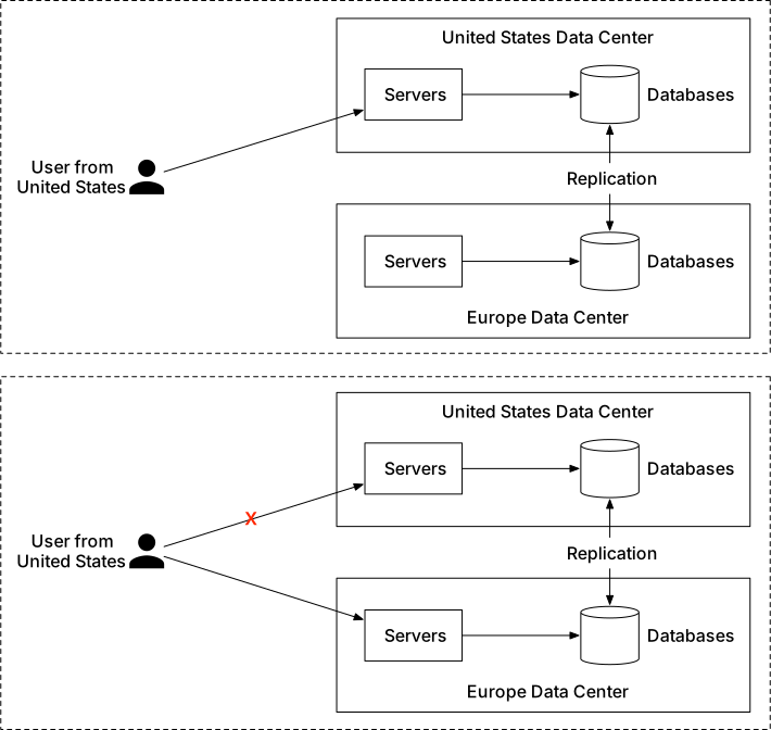
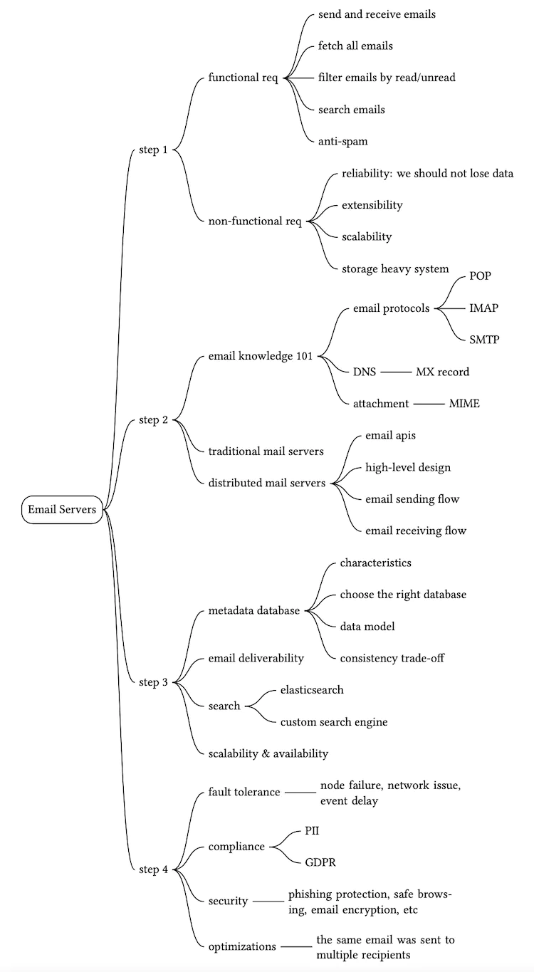
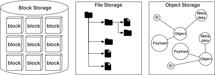
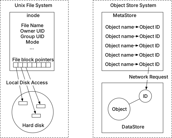
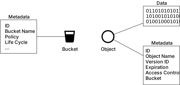
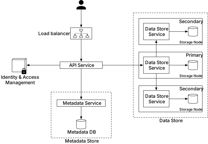
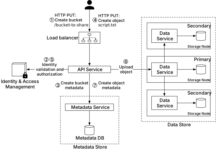
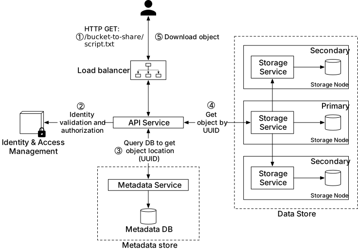
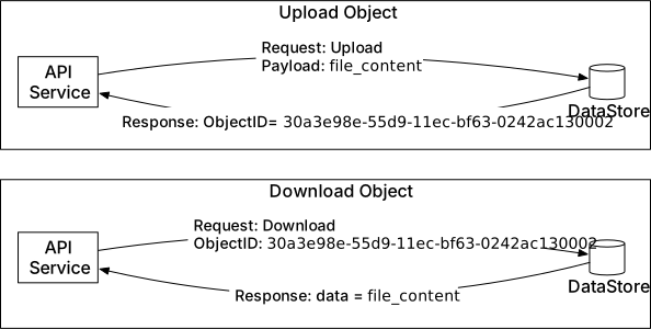
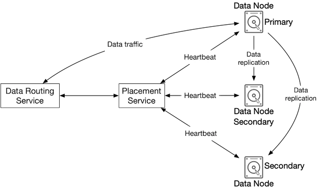
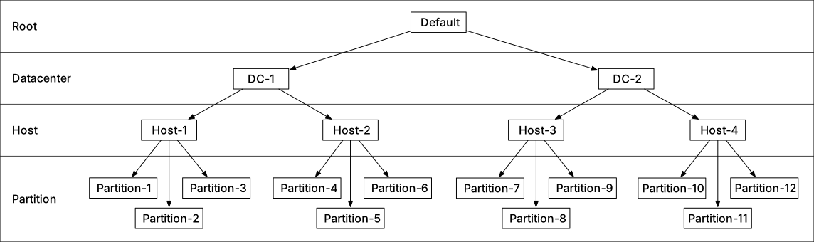
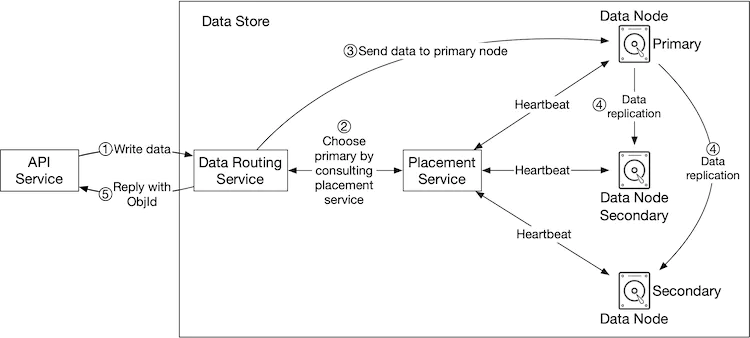
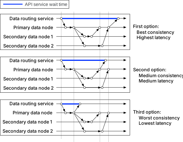
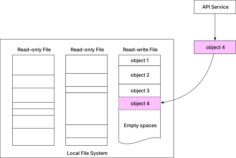
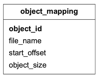
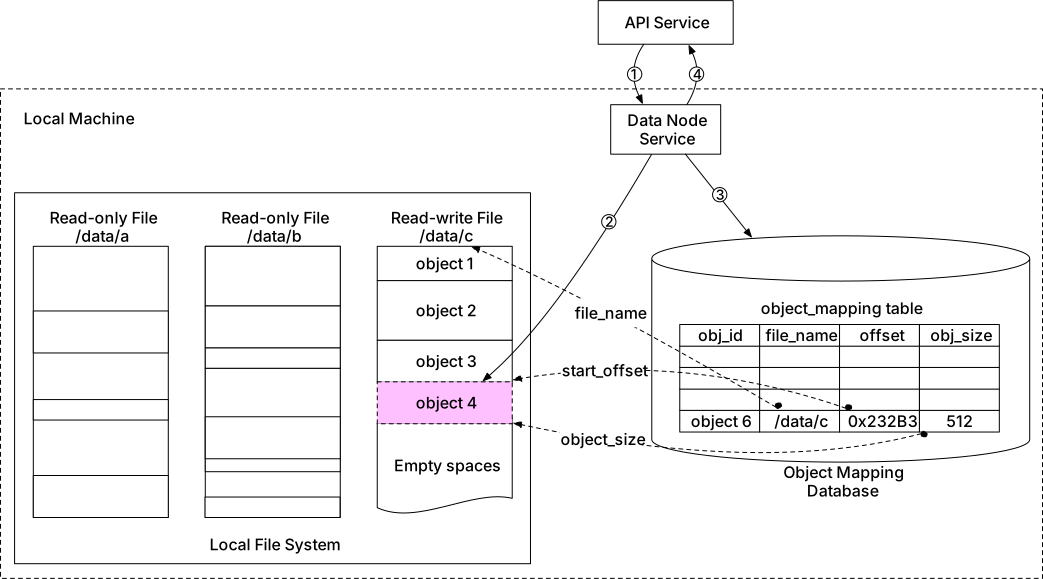
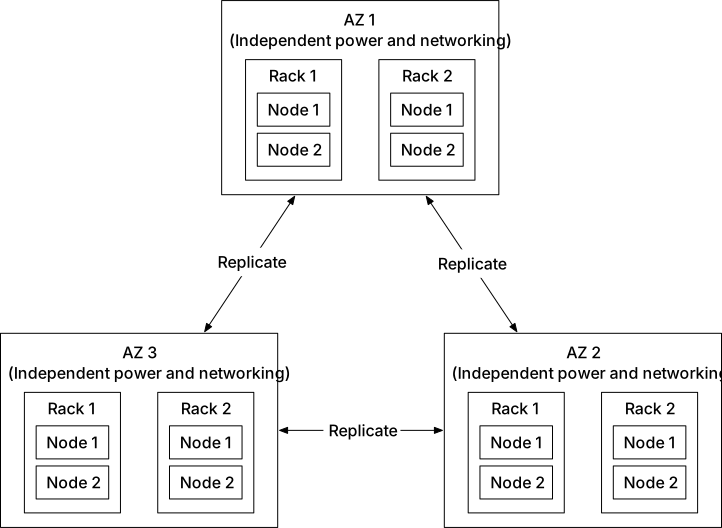
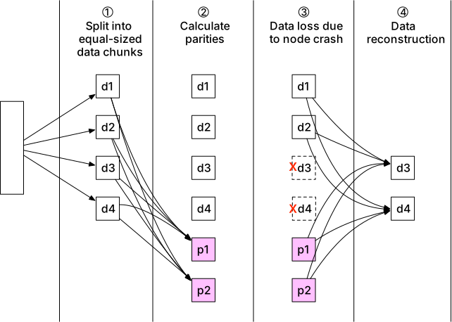
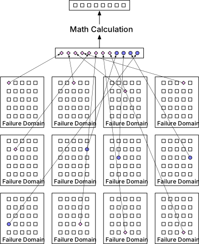
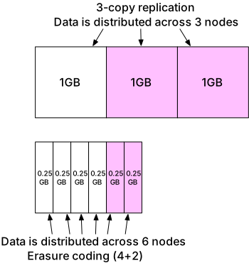


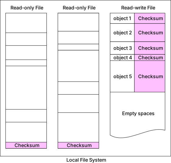
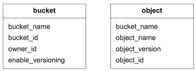
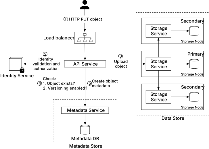
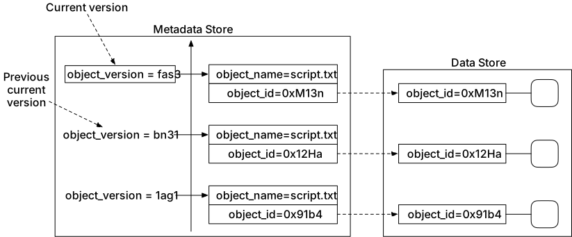
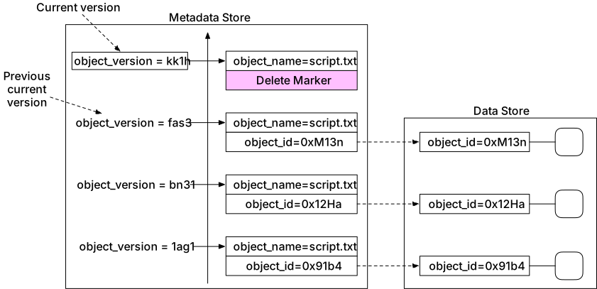
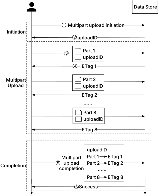
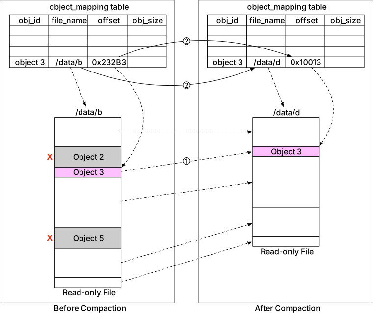
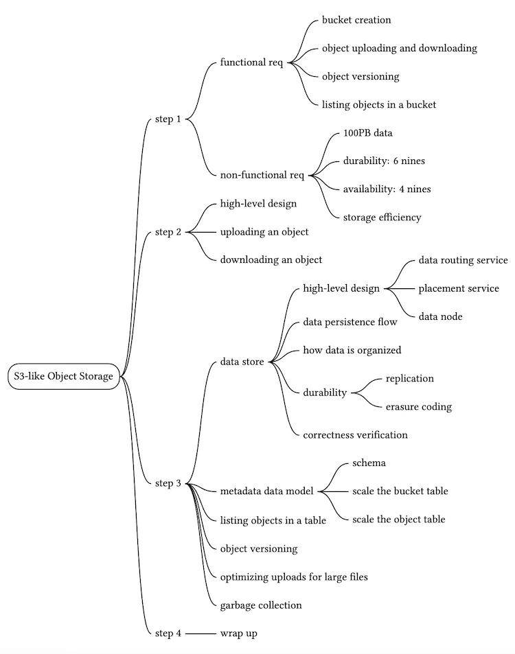
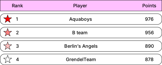
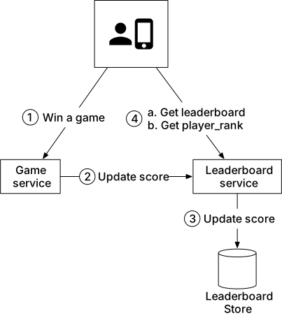
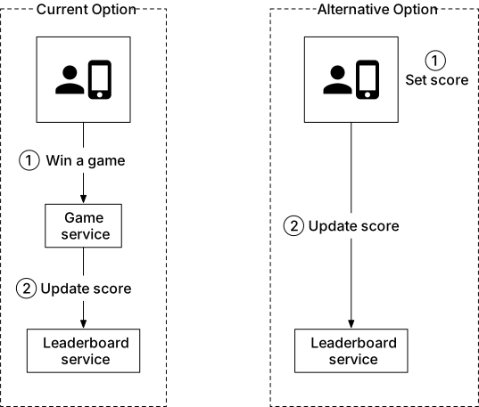
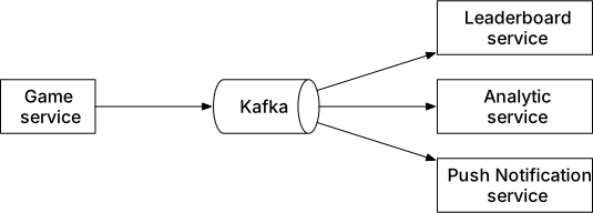
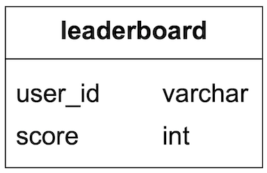


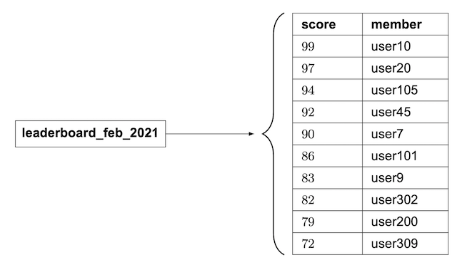
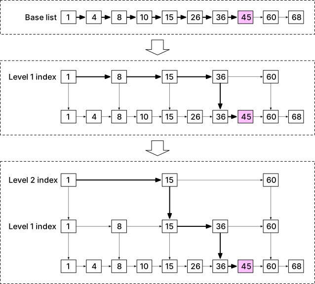




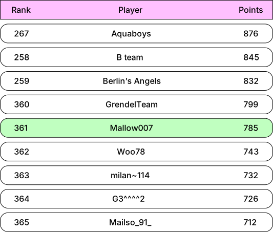
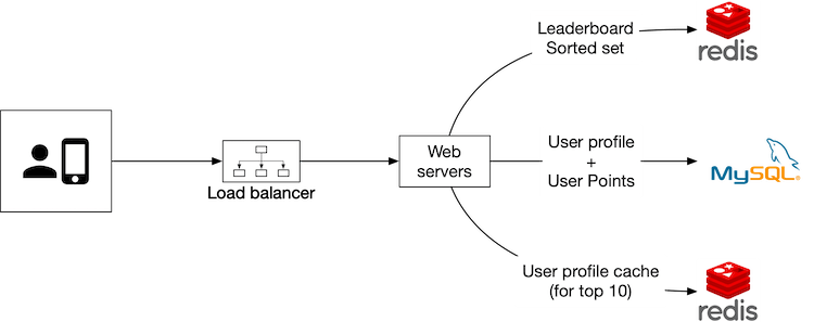
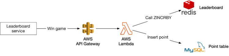
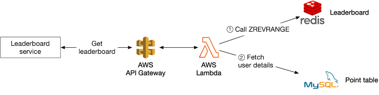

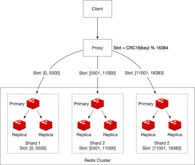
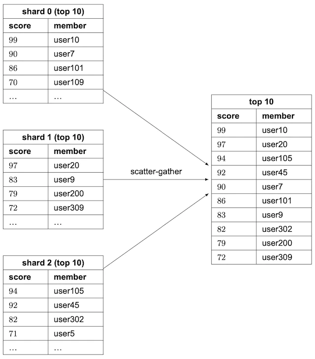

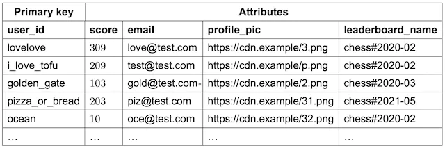

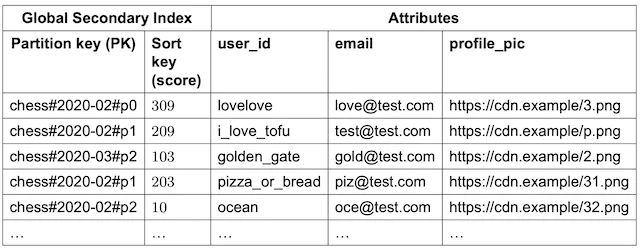
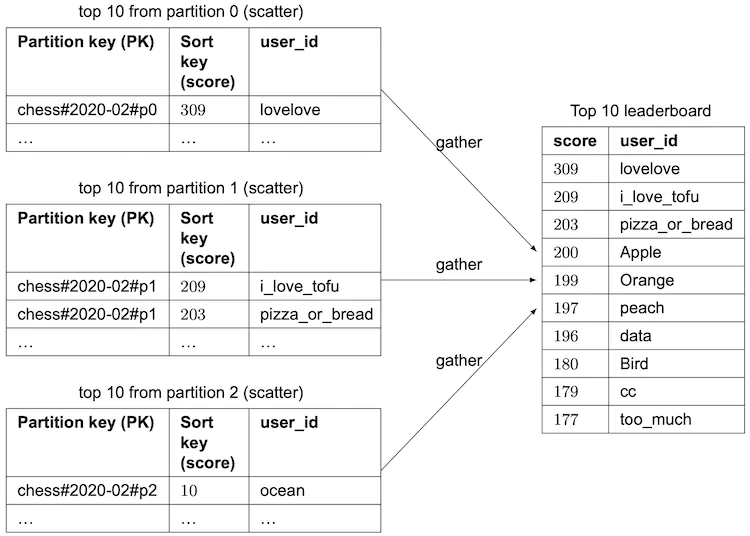
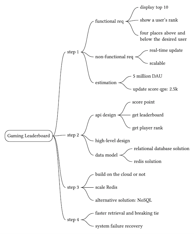
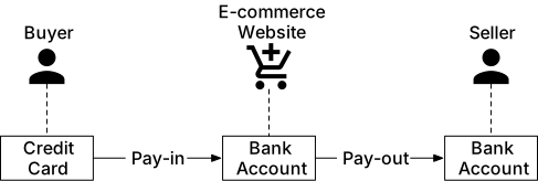
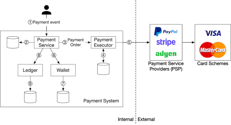
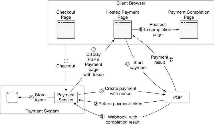
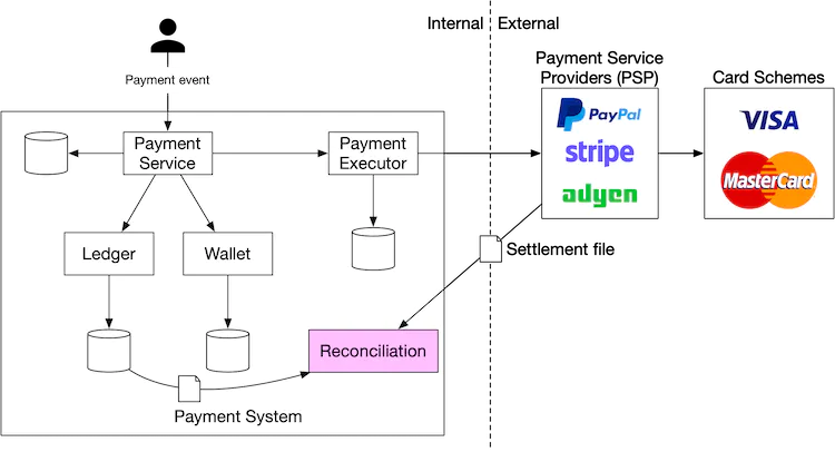
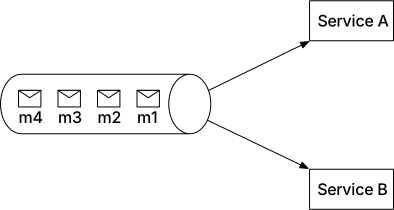
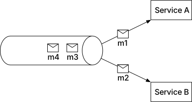
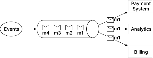
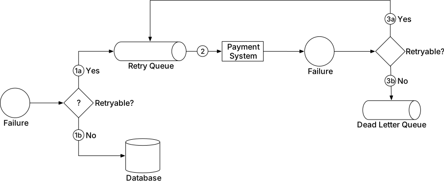
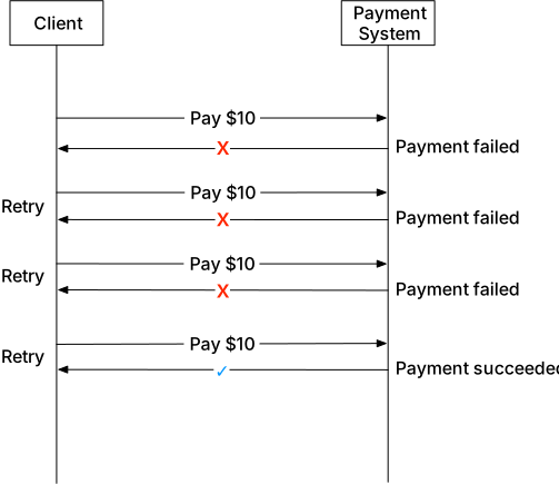
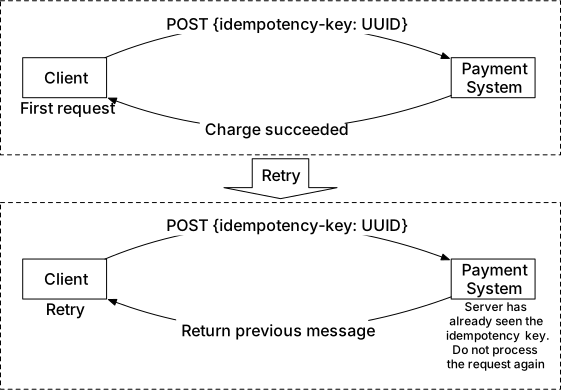
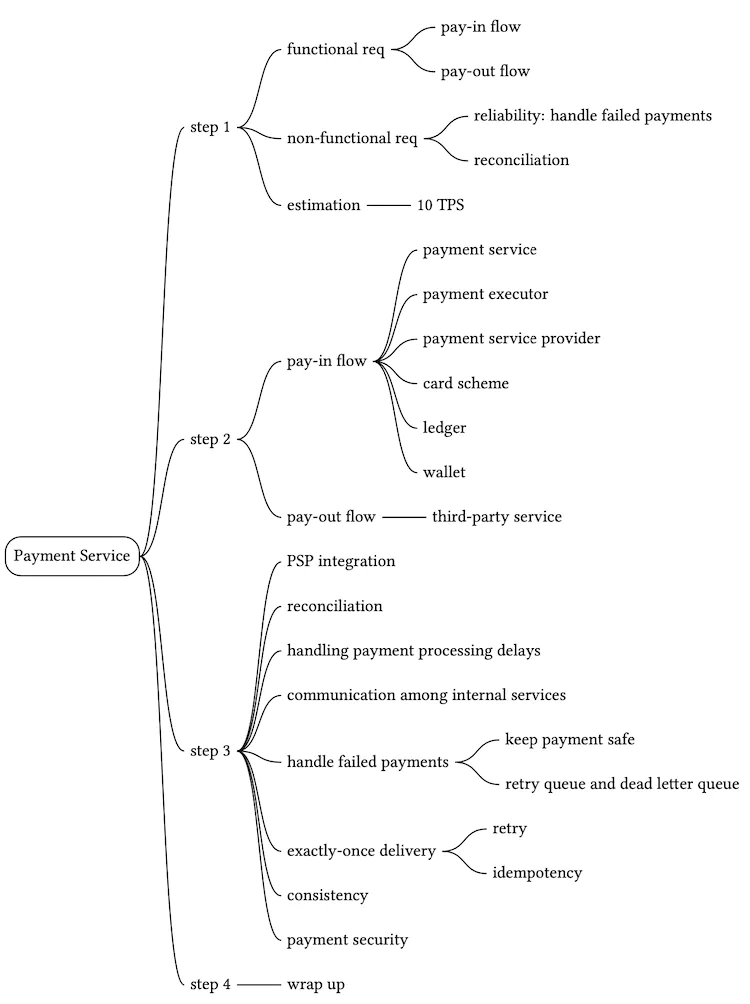

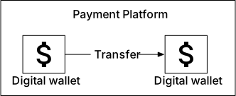
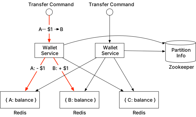
![Figure 5 Two-phase commit (source [5])](images/img_d3daf07fc030.svg)
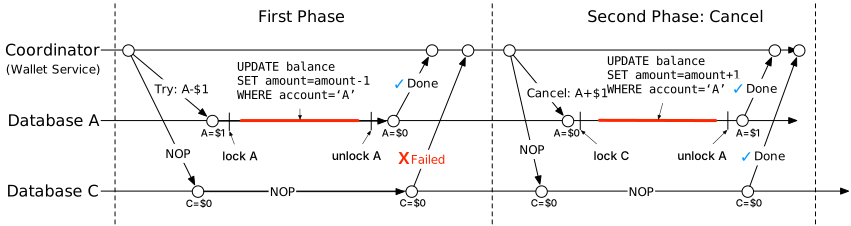
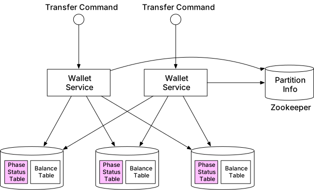
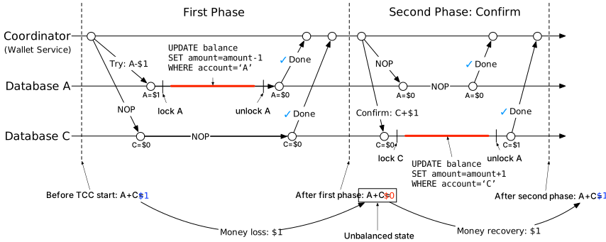
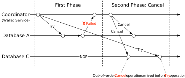
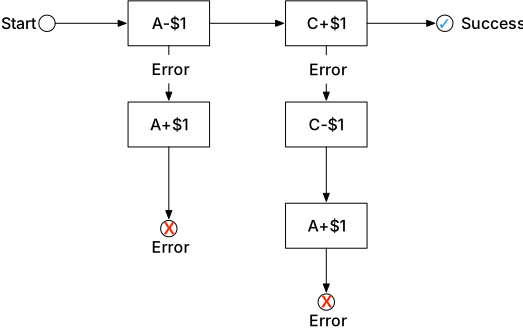
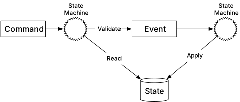
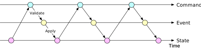
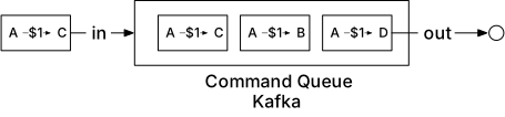
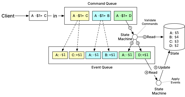
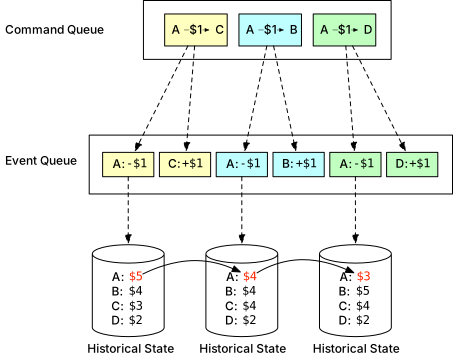
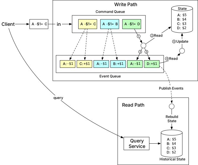
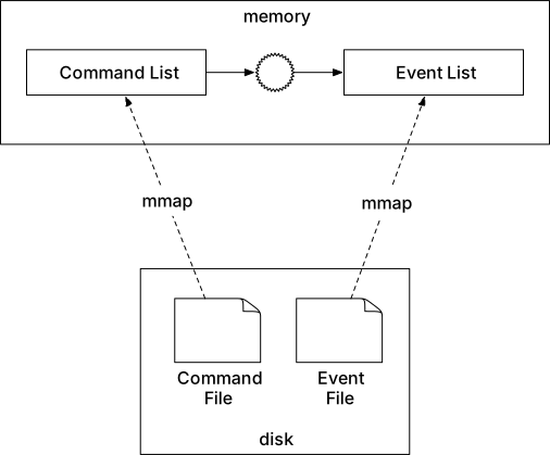

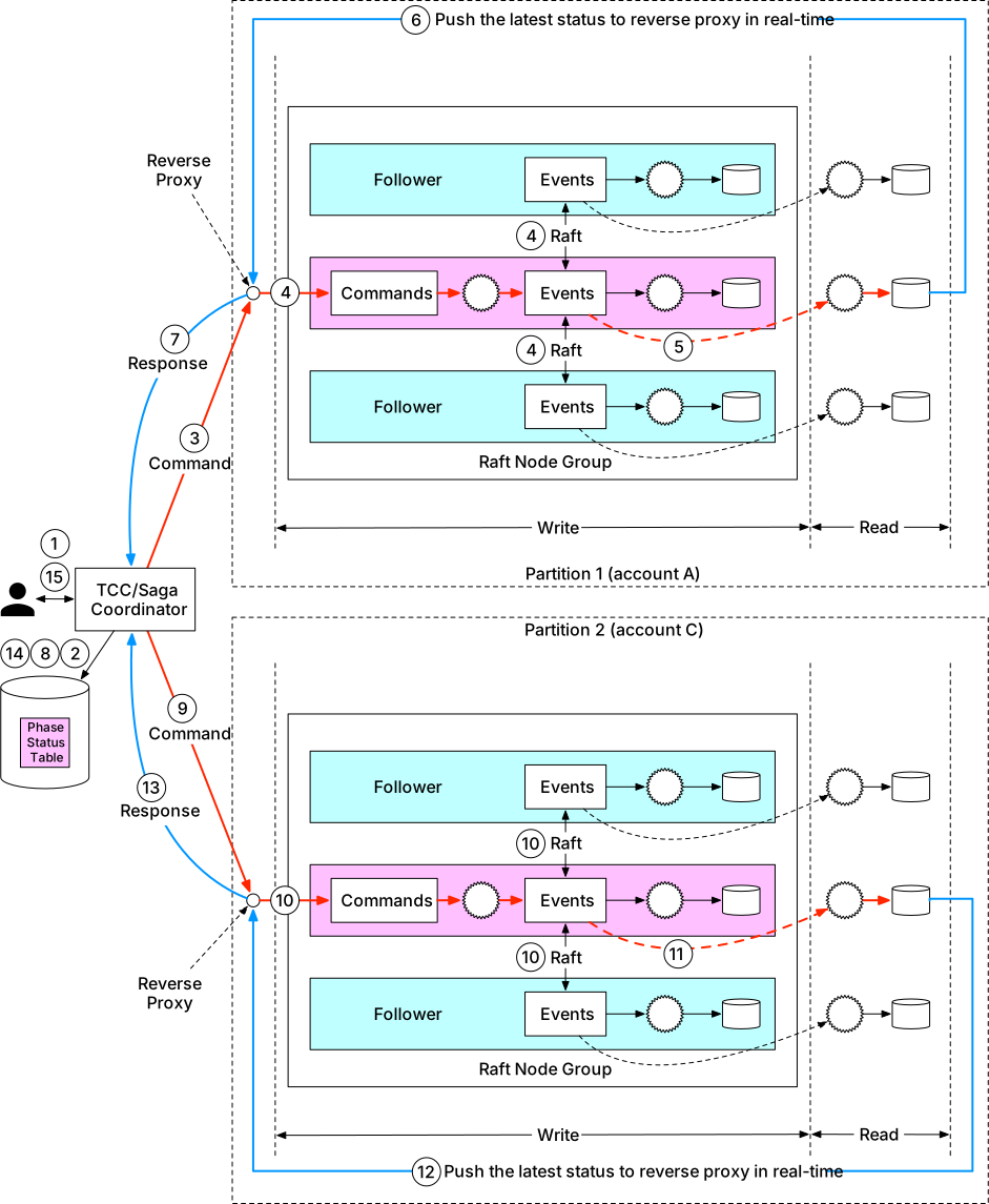
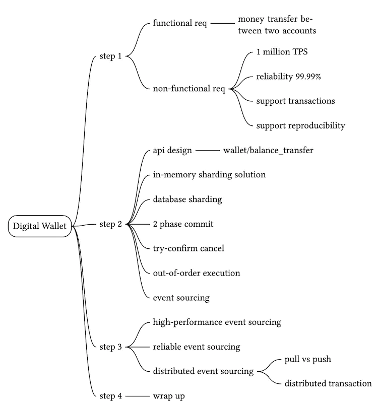
![Figure 1 Largest stock exchanges (Source: [5])](images/img_226da4515aa3.webp)
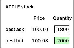
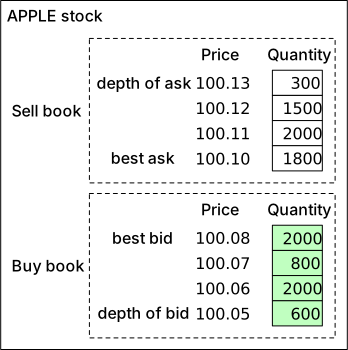
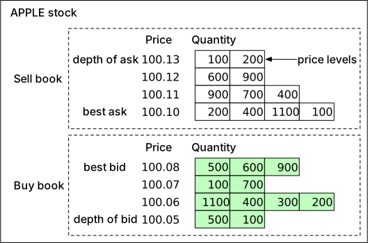
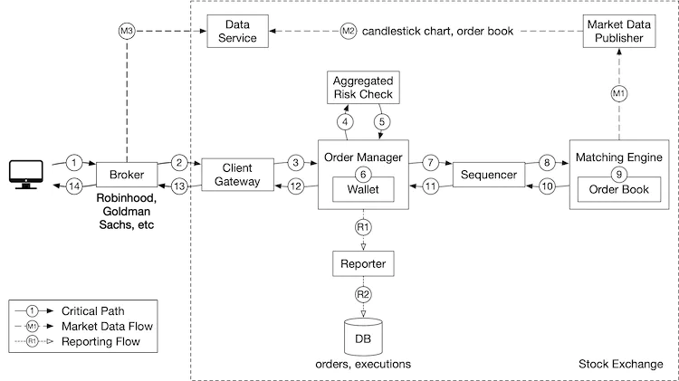
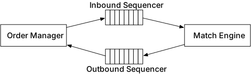
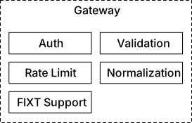
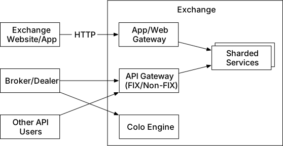
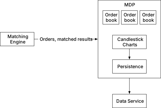
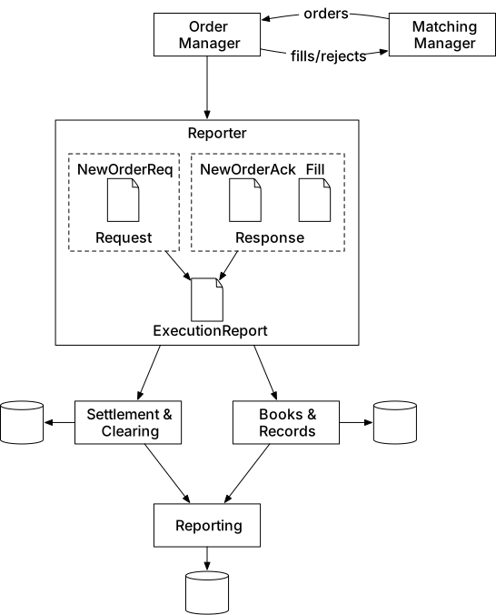
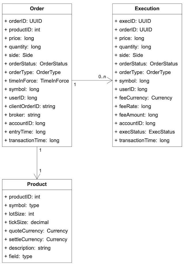
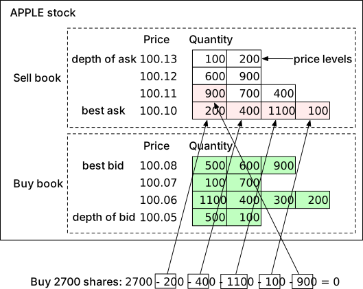
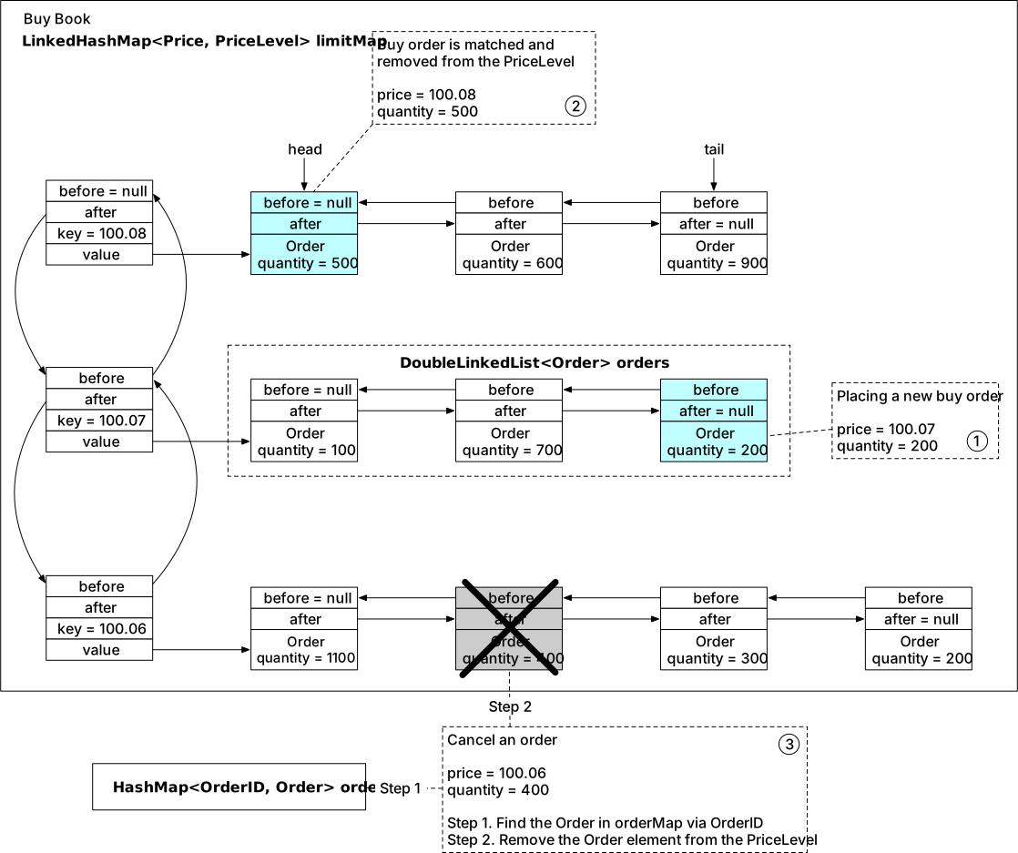
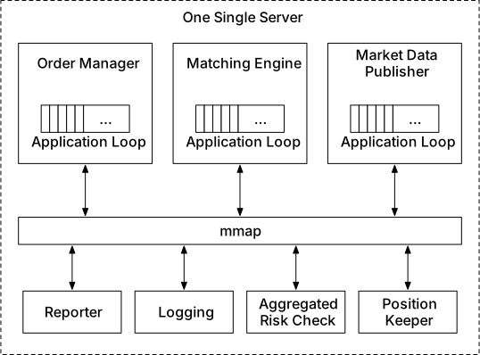
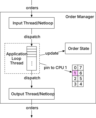
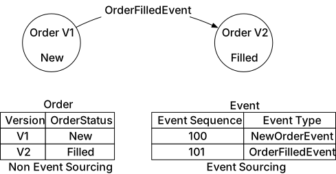
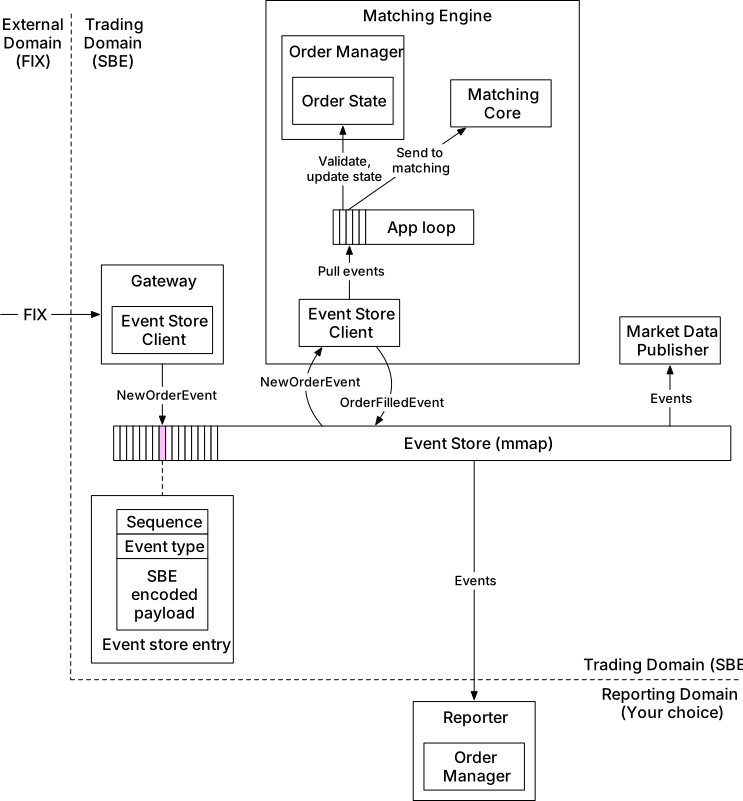
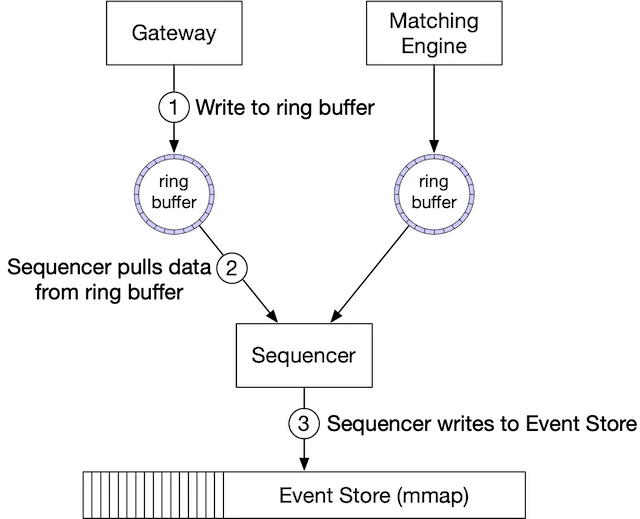
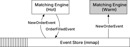
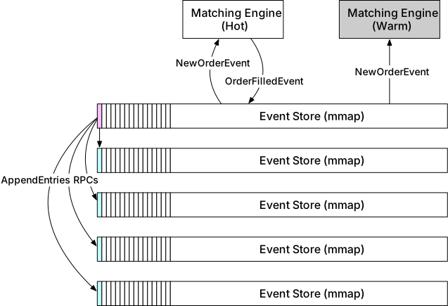
![Figure 22 Raft terms (Source: [23])](images/img_a0c07c17fc92.svg)
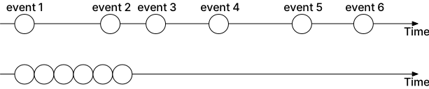
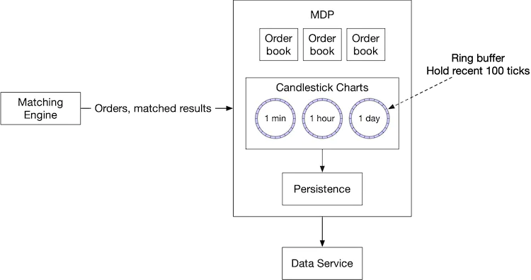
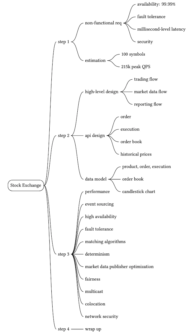
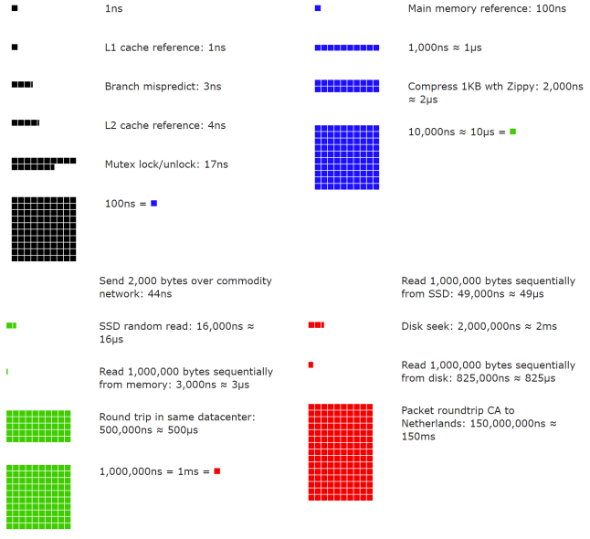
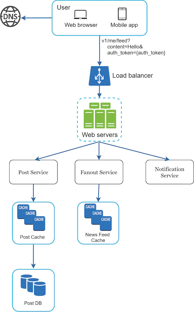
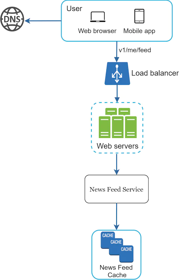
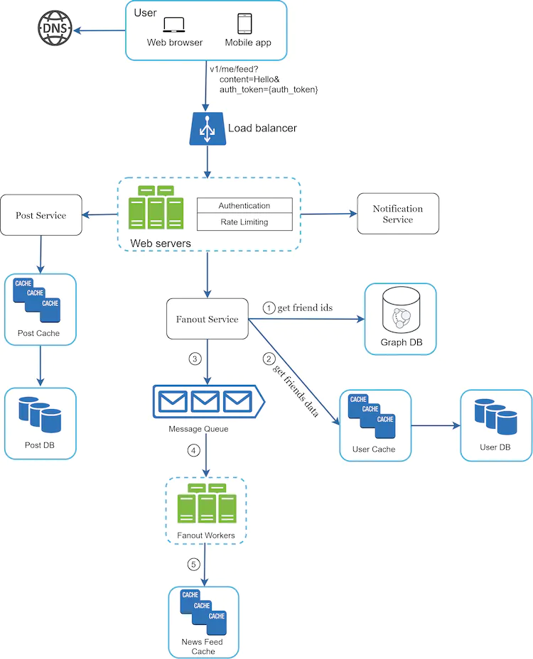
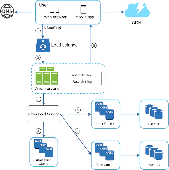
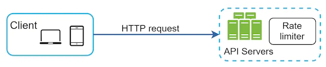
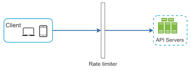
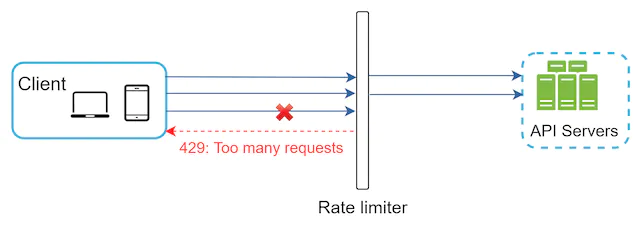


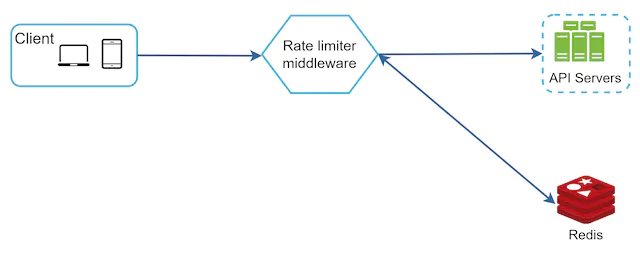
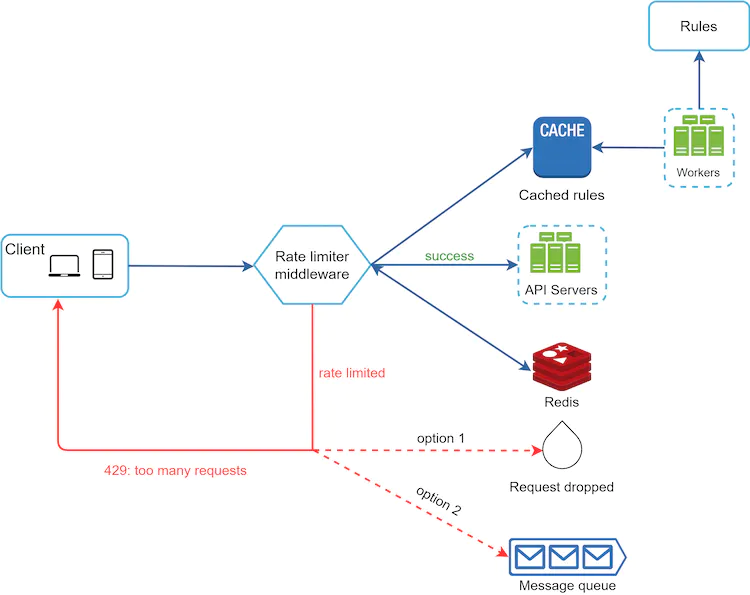

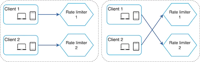
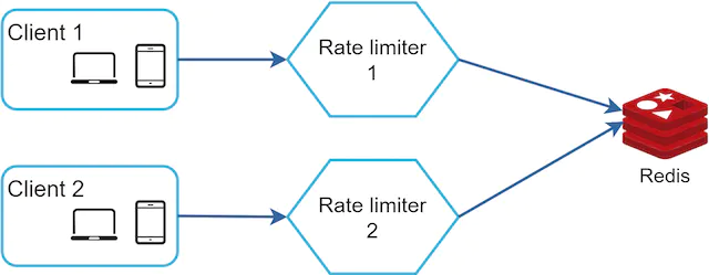
![Figure 17 (Source: [10])](images/img_25b2f7f65d5a.webp)